M2DC Series Hardware Manual
88
Rev. 1.1
2018/04
400-820-9661
7.3 Velocity Mode
The velocity control mode is used for applications that require precise velocity control. For M2DC series
servo drives, they are 4 types of velocity control mode: fixed-speed mode, analog command mode, SCL
control mode and multi-velocity control mode. Fixed-speed mode will set the motor running at a constant
speed. For analog command mode, velocity is controlled by external voltage input. SCL is a unique
software command tool of MOONS’. For multi-velocity control mode, the drive uses external inputs to set
up different velocity values. There are up to 8 different velocity values that can be set.
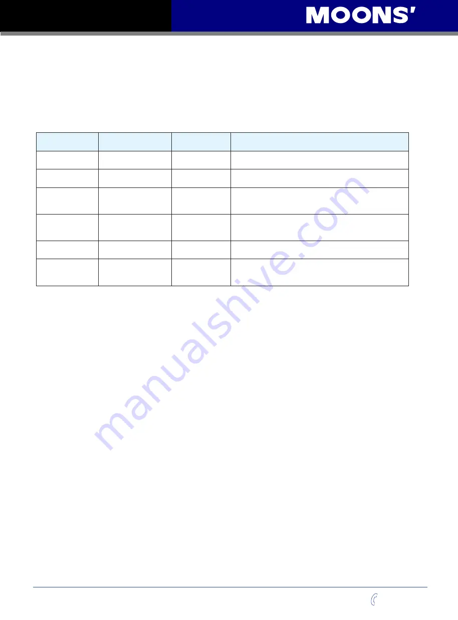
Mode
Control Signal
P-12 (CM)
Definitions
Description
Analog velocity
mode
+10~-10V Analog
signal
11
Analog velocity mode, NO run/stop signal, X2 is direction
switch.
Analog velocity
mode
+10~-10V Analog
signal
12
Analog velocity mode, X1 is run/stop signal, X2 is
direction switch.
Velocity Mode
Digital input signal
15
Profile velocity mode, after drive is enabled. The drive
will run at velocity set by P-22 (JS). NO run/stop signal,
X2 is direction switch
Velocity Mode
Digital input signal
16
Profile velocity mode, after drive is enabled. The drive
will run at velocity set by P-22 (JS). X1 is run/stop switch,
X2 is direction switch
In-position error
output
Digital output signal
17
Profile velocity mode, NO run/stop signal. X2 is direction
switch. X10, X11, X12 are speed selection switches.
In-position error
output
Digital output signal
18
Profile velocity mode, X1 is run/stop switch. X2 is
direction switch. X10, X11, X12 are speed selection
switches.
NOTE:We highly recommend using M Servo Suite software to configure velocity mode.


