71
Rev. 1.1
2018/04
400-820-9661
M2DC Series Hardware Manual
7 Operation Mode Selection
7.1 General Function Settings
7.1.1 Drive Servo On Settings
To control servo motor enable/disable switch
1) Servo ON signal
By default, the Servo ON input (X3) is configured as follows:
Signal Name
PIN (CN2)
Condition
Function
X3
29 (X3+)
31 (X3-)
Closed
Servo motor enable Servo ON
Open
Servo motor disable Servo OFF
2) Definition for Servo On signal
Parameters P-62 (SI) and P-14 (PM) can be changed
A. When P-14 (PM) = 2, parameter settings are as follows:
P-14 (PM)
P-62 (SI)
Condition
Function
P-14 (PM) = 2
(default)
1
Closed
If P-14 (PM)=2 and P-62 (SI)=2, driver will enable at
power-up, and then switch to disable
Open
Servo Enable
2
(default)
Closed
Servo motor enable Servo ON
Open
Servo motor disable Servo OFF
3
Enable servo motor when powered ON
B. When P-14 (PM) = 5, the parameter settings are as follows:
P-14 (PM)
P-62 (SI)
Condition
Function
P-14 (PM) = 5
1
Closed
Servo motor disable Servo OFF
Open
Servo motor enable Servo ON
2
(default)
Closed
Servo motor enable Servo ON
Open
Servo motor disable Servo OFF
3
Servo motor disable when power ON
NOTE: If P-14 (PM)=5, regardless of P-62 (SI) settings, the drive will be disabled (Servo OFF) at power up.
Use input X3 to enable based on P-62 (SI) setting.
The default Power-up Mode (PM) setting (P-14) is set to a value of 5, which will cause the servo drive to
power up disabled for safety during setup and configuration. This setting may be changed in the M Servo
Suite software with the X3 digital input configuration. It may also be changed using the front panel on the
servo drive with parameter P-14 or by using the PM command directly (see Host Command Reference
manual for details on the PM command.)
Software Configuration
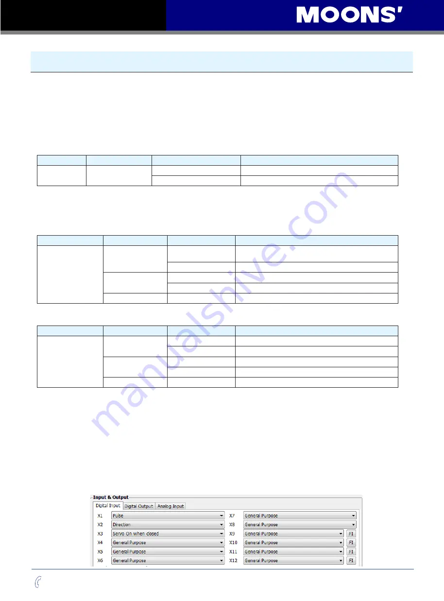
On the Drive Configuration page - Input & Output, select X3 function to set up.


