


213
Learning Advanced Features
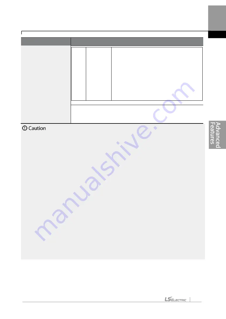
Code
Description
2
All (static
type)
Measures all parameters while the motor is
in the stopped position, including stator
resistance (Rs), no-load current (Noload
Curr), rotor time constant (Tr), etc. Since the
motor is not rotating while the parameters
are measured, the measurements are not
affected when the load is connected to the
motor spindle. However, when measuring
parameters, do not rotate the motor spindle
on the load side.
BAS-14 Noload Curr,
BAS-21 Rs
–BAS-24 Tr
Displays motor parameters measured by auto tuning. For
parameters that are not included in the auto tuning measurement
list, the default setting will be displayed.
•
Perform auto tuning ONLY after the motor has completely stopped running.
•
Auto tuning operates when the inverter’s auto mode is off.
•
Before you run auto tuning, check the motor pole number, rated slip, rated current, rated
volta
ge, and efficiency on the motor’s rating plate and enter the data. The default
parameter setting is used for values that are not entered.
•
When measuring all parameters after selecting 2 ( All-static type) at BAS-20: compared
with rotation type auto tuning where parameters are measured while the motor is rotating,
parameter values measured with static auto tuning may be less accurate. Inaccuracy of the
measured parameters may degrade the performance of operations. Therefore, run static-
type auto tuning by selecting 2 (All) only when the motor cannot be rotated (when gearing
and belts cannot be separated easily, or when the motor cannot be separated mechanically
from the load).
•
If auto tuning operates without wiring the motor,
‘Rs Tune Err’ or ‘Lsig Tune Err’ warning
messages are displayed. It can be reset if you press
‘STOP/RESET’ button of the keypad.
5.22 Time Event Scheduling
Содержание LSLV-H100 Series
Страница 17: ...Preparing the Installation 4 37 90 kW 3 Phase ...
Страница 18: ...Preparing the Installation 5 110 132 kW 3 Phase ...
Страница 19: ...Preparing the Installation 6 160 185 kW 3 Phase ...
Страница 20: ...Preparing the Installation 7 220 250 kW 3 Phase ...
Страница 21: ...Preparing the Installation 8 315 400 kW 3 Phase ...
Страница 22: ...Preparing the Installation 9 500 kW 3 Phase ...
Страница 35: ...Installing the Inverter 22 ...
Страница 50: ...37 Installing the Inverter Input and Output Control Terminal Block Wiring Diagram ...
Страница 104: ...91 Learning Basic Features 0 10 V Input Voltage Setting Details V1 Quantizing ...
Страница 181: ...168 Learning Advanced Features PID Command Block ...
Страница 182: ...169 Learning Advanced Features ...
Страница 183: ...170 Learning Advanced Features PID Feedback Block ...
Страница 184: ...171 Learning Advanced Features PID Output Block ...
Страница 185: ...172 Learning Advanced Features PID Output Mode Block ...
Страница 198: ...185 Learning Advanced Features EPID1 Control block ...
Страница 199: ...186 Learning Advanced Features EPID2 Control block ...
Страница 220: ...207 Learning Advanced Features ...
Страница 235: ...222 Learning Advanced Features The Time Chart for the Exception Day ...
Страница 506: ...Table of Functions 493 ...
Страница 520: ...Table of Functions 507 8 16 4 Cooling Tower MC4 Group ...
Страница 549: ...Troubleshooting 536 ...
Страница 569: ...Technical Specification 556 11 3 External Dimensions 0 75 30 kW 3 phase 37 90 kW 3 phase ...
Страница 570: ...Technical Specification 557 110 185 kW 3 phase ...
Страница 601: ...588 ...
Страница 602: ...589 ...
Страница 603: ...590 ...


