


275
Learning Advanced Features
AP1-61
AP1-62
AP1-63
AP1-64
AP1-65
Max Freq
Frequency
AP1-71
AP1-72
Aux Motor 1
Aux Motor 2
Aux Motor 3
Aux Motor 4
Aux Motor 5
Feedback
AP1-71
AP1-72
Perform Main_Exch
Reset the [Auto Op Time]
AP1-62
AP1-63
0%
100%
Fx
Off
On
Stop
Run
Inv State
Main Motor
Main Motor
5min
10min
30min
Operation time
M1(30min) / M2(25min) /
M3(20min)
Pr iority at the moment
M1
M2
M3 /
M4
M5
Pr iority at the moment
M1
M3
M2 /
M4
M5
Pr iority at the moment
M4
M5
M3 /
M2
M1
Supposing its operation in
less than 1minute
AP1-65
AP1-
74
Motor to operate MMC :
M1
, M2, M3
Standby motor : M4, M5
Motor to operate MMC : M3,
M4
, M5
Standby motor : M1, M2
AP1-72
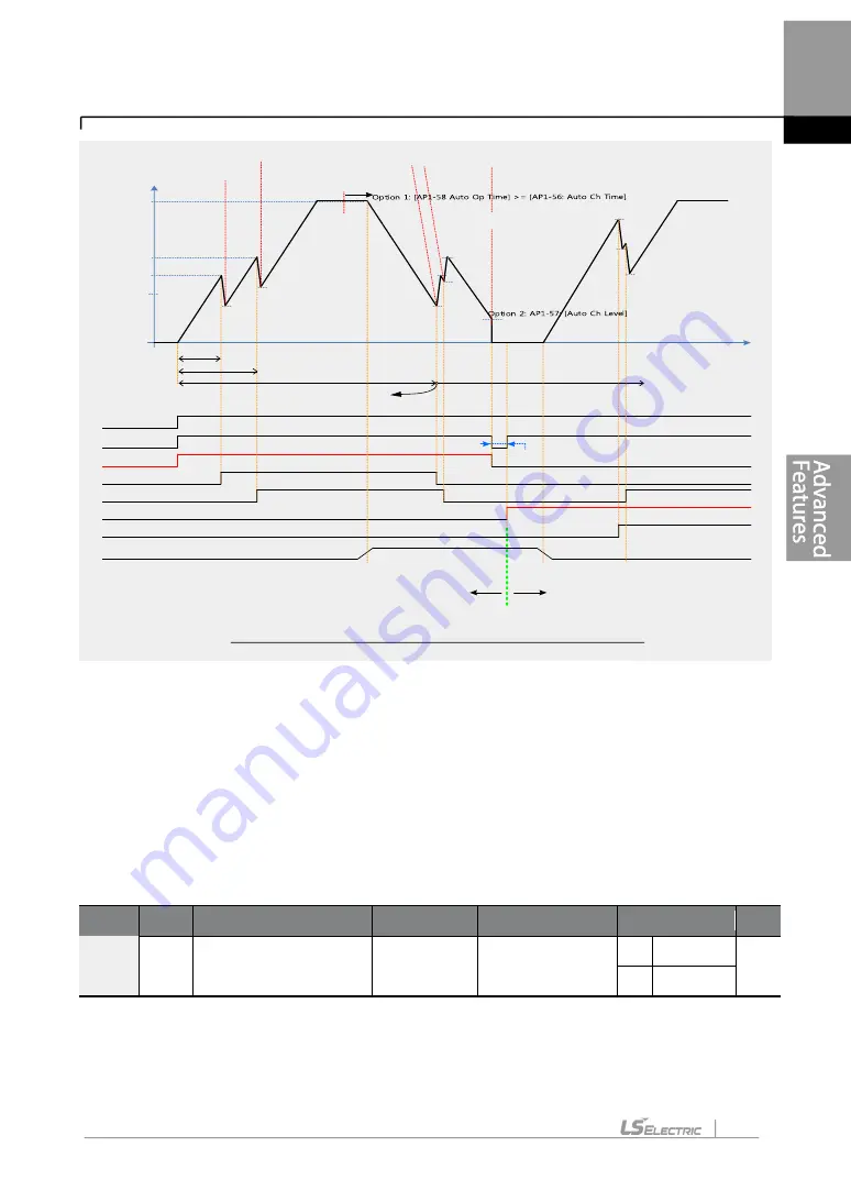
Main Auto Change operation (Op Time Order) when Operable Motor and Standby Motor are set to 3 and 2 each
Option 3: AP1-91: [Interlock DT]
5.44.4 Interlock
When there is motor trouble, the interlock feature is used to stop the affected motor and
replace it with another that is not currently operating (off state). To activate the interlock
feature, connect the cables for abnormal motor signal to the inverter input terminal and
configure the terminals as interlock 1
–5 inputs. Then, the inverter decides the motor’s
availability based on the signal inputs. The order in which the alternative motor is selected is
decided based on the auto change mode selection options set at AP1-55.
Group Code Name
LCD Display Parameter Setting Setting Range Unit
AP1
90
Interlock selection
Interlock
1
0
NO
-
1
YES
After configuring the IN-65
–71 multi-purpose input terminals as Interlock input 1–5, if an
interlock signal is received from an auxiliary motor, the output contacts are turned off for the
motor and the motor is excluded from the MMC operation. This causes the priority level of
the auxiliary motors with lower priority level than the interlocked motor to be increased by 1.
Содержание LSLV-H100 Series
Страница 17: ...Preparing the Installation 4 37 90 kW 3 Phase ...
Страница 18: ...Preparing the Installation 5 110 132 kW 3 Phase ...
Страница 19: ...Preparing the Installation 6 160 185 kW 3 Phase ...
Страница 20: ...Preparing the Installation 7 220 250 kW 3 Phase ...
Страница 21: ...Preparing the Installation 8 315 400 kW 3 Phase ...
Страница 22: ...Preparing the Installation 9 500 kW 3 Phase ...
Страница 35: ...Installing the Inverter 22 ...
Страница 50: ...37 Installing the Inverter Input and Output Control Terminal Block Wiring Diagram ...
Страница 104: ...91 Learning Basic Features 0 10 V Input Voltage Setting Details V1 Quantizing ...
Страница 181: ...168 Learning Advanced Features PID Command Block ...
Страница 182: ...169 Learning Advanced Features ...
Страница 183: ...170 Learning Advanced Features PID Feedback Block ...
Страница 184: ...171 Learning Advanced Features PID Output Block ...
Страница 185: ...172 Learning Advanced Features PID Output Mode Block ...
Страница 198: ...185 Learning Advanced Features EPID1 Control block ...
Страница 199: ...186 Learning Advanced Features EPID2 Control block ...
Страница 220: ...207 Learning Advanced Features ...
Страница 235: ...222 Learning Advanced Features The Time Chart for the Exception Day ...
Страница 506: ...Table of Functions 493 ...
Страница 520: ...Table of Functions 507 8 16 4 Cooling Tower MC4 Group ...
Страница 549: ...Troubleshooting 536 ...
Страница 569: ...Technical Specification 556 11 3 External Dimensions 0 75 30 kW 3 phase 37 90 kW 3 phase ...
Страница 570: ...Technical Specification 557 110 185 kW 3 phase ...
Страница 601: ...588 ...
Страница 602: ...589 ...
Страница 603: ...590 ...


