


80
Learning Basic Features
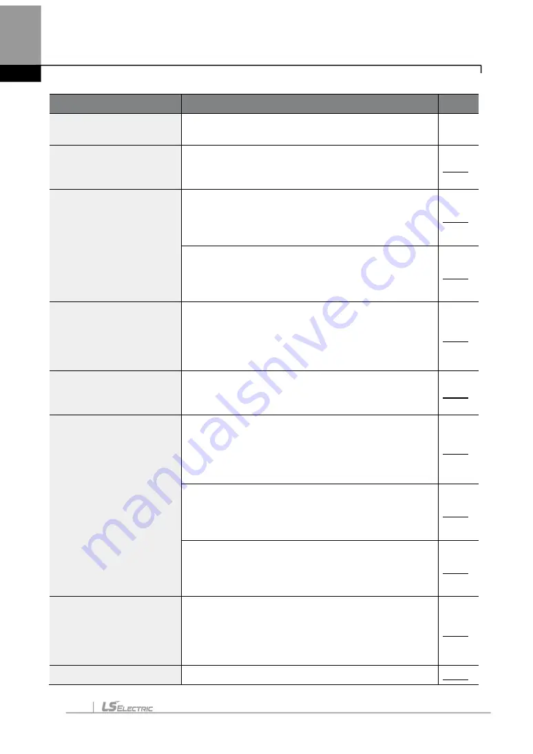
Basic Tasks
Description
Ref.
operation
torque. To maintain the required torque, the operating
frequency may vary during operation.
Square reduction V/F
pattern operation
Configures the inverter to run the motor at a square
reduction V/F pattern. Fans and pumps are
appropriate loads for square reduction V/F operation.
User V/F pattern
configuration
Enables the user to configure a V/F pattern to match
the characteristics of a motor. This configuration is for
special-purpose motor applications to achieve optimal
performance.
Manual torque boost
Manual configuration of the inverter to produce a
momentary torque boost. This configuration is for
loads that require a large amount of starting torque,
such as elevators or lifts.
Automatic torque boost
Automatic configuration of the inverter that
provides
”auto tuning” that produces a momentary
torque boost. This configuration is for loads that
require a large amount of starting torque, such as
elevators or lifts.
Output voltage adjustment
Adjusts the output voltage to the motor when the
power supply to the inverter differs from the motor’s
rated input voltage.
Accelerating start
Accelerating start is the general way to start motor
operation. The typical application configures the motor
to accelerate to a target frequency in response to a run
command, however there may be other start or
acceleration conditions defined.
Start after DC braking
Configures the inverter to perform DC braking before
the motor starts rotating again. This configuration is
used when the motor will be rotating before the voltage
is supplied from the inverter.
Deceleration stop
Deceleration stop is the typical method used to stop a
motor. The motor decelerates to 0 Hz and stops on a
stop command, however there may be other stop or
deceleration conditions defined.
Stopping by DC braking
Configures the inverter to apply DC braking during
motor deceleration. The frequency at which DC
braking occurs must be defined and during
deceleration, when the motor reaches the defined
frequency, DC braking is applied.
Free-run stop
Configures the inverter to stop output to the motor
Содержание LSLV-H100 Series
Страница 17: ...Preparing the Installation 4 37 90 kW 3 Phase ...
Страница 18: ...Preparing the Installation 5 110 132 kW 3 Phase ...
Страница 19: ...Preparing the Installation 6 160 185 kW 3 Phase ...
Страница 20: ...Preparing the Installation 7 220 250 kW 3 Phase ...
Страница 21: ...Preparing the Installation 8 315 400 kW 3 Phase ...
Страница 22: ...Preparing the Installation 9 500 kW 3 Phase ...
Страница 35: ...Installing the Inverter 22 ...
Страница 50: ...37 Installing the Inverter Input and Output Control Terminal Block Wiring Diagram ...
Страница 104: ...91 Learning Basic Features 0 10 V Input Voltage Setting Details V1 Quantizing ...
Страница 181: ...168 Learning Advanced Features PID Command Block ...
Страница 182: ...169 Learning Advanced Features ...
Страница 183: ...170 Learning Advanced Features PID Feedback Block ...
Страница 184: ...171 Learning Advanced Features PID Output Block ...
Страница 185: ...172 Learning Advanced Features PID Output Mode Block ...
Страница 198: ...185 Learning Advanced Features EPID1 Control block ...
Страница 199: ...186 Learning Advanced Features EPID2 Control block ...
Страница 220: ...207 Learning Advanced Features ...
Страница 235: ...222 Learning Advanced Features The Time Chart for the Exception Day ...
Страница 506: ...Table of Functions 493 ...
Страница 520: ...Table of Functions 507 8 16 4 Cooling Tower MC4 Group ...
Страница 549: ...Troubleshooting 536 ...
Страница 569: ...Technical Specification 556 11 3 External Dimensions 0 75 30 kW 3 phase 37 90 kW 3 phase ...
Страница 570: ...Technical Specification 557 110 185 kW 3 phase ...
Страница 601: ...588 ...
Страница 602: ...589 ...
Страница 603: ...590 ...


