Troubleshooting Hardware Components
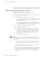
turns off the power supplies. The following conditions automatically cause the fans
and impellers to run at full speed and also trigger the indicated alarm:
A fan or impeller fails (red alarm).
One of the impellers is removed (yellow alarm).
The router temperature exceeds the “temperature warm” threshold (yellow
alarm).
The temperature of the router exceeds the maximum (“temperature hot”)
threshold (red alarm and automatic shutdown of the power supplies).
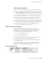
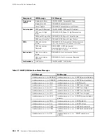
For more information about impeller-related alarms, see “Chassis and
Interface Alarm Messages” on page 209.
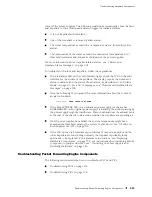
To troubleshoot the fans and impellers, follow these guidelines:
If the red alarm LED on the craft interface lights, check the LCD on the craft
interface for the source of the problem. The display reports the number of
alarm conditions and the source of each alarm, as described in “LCD Alarm
Mode” on page 30. For a list of messages, see “Chassis and Interface Alarm
Messages” on page 209.
Issue the following CLI command for more information about the source of
an alarm condition:
user@host> show chassis alarms
If the blue
OUTPUT OK
LED on an enhanced power supply (or the amber
NO AIRFLOW
LED on an original power supply) is blinking, the airflow passing by
the power supply might be insufficient. Place your hand near the exhaust vents
at the rear of the chassis to determine whether the impellers are expelling air.
If both power supplies have failed, the system temperature might have
exceeded the threshold, causing the system to shut down. See “All LEDs on
Both Supplies Are Off” on page 215.
If the LCD on the craft interface reports failure of only one impeller and the
other impellers are functioning normally, the impeller is probably faulty
and needs to be replaced. For replacement instructions, see “Replacing
Hardware Components” on page 139. For instructions about returning a faulty
component to Juniper Networks, see “Contacting Customer Support and
Returning Hardware” on page 255.
Troubleshooting Packet Forwarding Engine Components
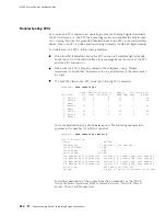
The following sections describe how to troubleshoot FPCs and PICs:
Troubleshooting FPCs on page 214
Troubleshooting PICs on page 215
Troubleshooting Packet Forwarding Engine Components
213
Содержание Internet Router M160
Страница 12: ...M160 Internet Router Hardware Guide xii Table of Contents ...
Страница 16: ...M160 Internet Router Hardware Guide xvi List of Figures ...
Страница 18: ...M160 Internet Router Hardware Guide xviii List of Tables ...
Страница 24: ...M160 Internet Router Hardware Guide xxiv Requesting Support ...
Страница 26: ...2 Product Overview ...
Страница 30: ...M160 Internet Router Hardware Guide 6 Safety Requirements Warnings and Guidelines ...
Страница 66: ...M160 Internet Router Hardware Guide 42 Cable Management System ...
Страница 80: ...M160 Internet Router Hardware Guide 56 Routing Engine Architecture ...
Страница 82: ...58 Initial Installation ...
Страница 104: ...M160 Internet Router Hardware Guide 80 Unpacking the Router ...
Страница 148: ...M160 Internet Router Hardware Guide 124 Configuring the JUNOS Internet Software ...
Страница 150: ...126 Hardware Maintenance Replacement and Troubleshooting Procedures ...
Страница 242: ...M160 Internet Router Hardware Guide 218 Troubleshooting the Power System ...
Страница 244: ...220 Appendixes ...
Страница 292: ...M160 Internet Router Hardware Guide 268 Packing Components for Shipment ...
Страница 301: ...Part 5 Index Index 277 ...
Страница 302: ...278 Index ...

