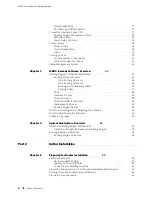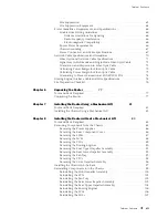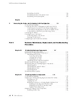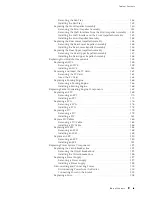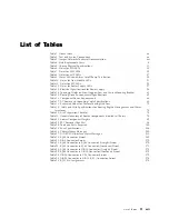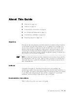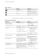
List of Figures
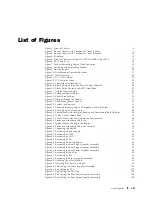
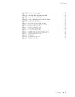
Figure 1: Front of Chassis . . . . . . . . . . . . . . . . . . . . . . . . . . . . . . . . . . . . . . . . . . . . . . . . . . . . . . . . . . . . . . . . . . . . . . . . 8
Figure 2: Rear of Chassis with Component Cover in Place . . . . . . . . . . . . . . . . . . . . . . . . . . . . . . . . . . . . . 9
Figure 3: Rear of Chassis with Component Cover Removed . . . . . . . . . . . . . . . . . . . . . . . . . . . . . . . . . . 10
Figure 4: Midplane. . . . . . . . . . . . . . . . . . . . . . . . . . . . . . . . . . . . . . . . . . . . . . . . . . . . . . . . . . . . . . . . . . . . . . . . . . . . . . . 13
Figure 5: Front of Chassis with Four-PIC FPC Installed in Slot FPC0 . . . . . . . . . . . . . . . . . . . . . . . . . . 15
Figure 6: FPC1 and FPC2. . . . . . . . . . . . . . . . . . . . . . . . . . . . . . . . . . . . . . . . . . . . . . . . . . . . . . . . . . . . . . . . . . . . . . . . 18
Figure 7: Packet Forwarding Engine Clock Generator. . . . . . . . . . . . . . . . . . . . . . . . . . . . . . . . . . . . . . . . . . 19
Figure 8: Switching and Forwarding Module . . . . . . . . . . . . . . . . . . . . . . . . . . . . . . . . . . . . . . . . . . . . . . . . . . . 21
Figure 9: Routing Engine . . . . . . . . . . . . . . . . . . . . . . . . . . . . . . . . . . . . . . . . . . . . . . . . . . . . . . . . . . . . . . . . . . . . . . . . 25
Figure 10: Miscellaneous Control Subsystem. . . . . . . . . . . . . . . . . . . . . . . . . . . . . . . . . . . . . . . . . . . . . . . . . . . 27
Figure 11: Craft Interface . . . . . . . . . . . . . . . . . . . . . . . . . . . . . . . . . . . . . . . . . . . . . . . . . . . . . . . . . . . . . . . . . . . . . . . . 28
Figure 12: LCD in Idle Mode . . . . . . . . . . . . . . . . . . . . . . . . . . . . . . . . . . . . . . . . . . . . . . . . . . . . . . . . . . . . . . . . . . . . 30
Figure 13: LCD in Alarm Mode. . . . . . . . . . . . . . . . . . . . . . . . . . . . . . . . . . . . . . . . . . . . . . . . . . . . . . . . . . . . . . . . . . 30
Figure 14: Connector Interface Panel. . . . . . . . . . . . . . . . . . . . . . . . . . . . . . . . . . . . . . . . . . . . . . . . . . . . . . . . . . . 33
Figure 15: Routing Engine Interface Ports for Host Module 0 . . . . . . . . . . . . . . . . . . . . . . . . . . . . . . . . 34
Figure 16: Alarm Relay Contacts and BITS Input Ports . . . . . . . . . . . . . . . . . . . . . . . . . . . . . . . . . . . . . . . . 35
Figure 17: Original Power Supply . . . . . . . . . . . . . . . . . . . . . . . . . . . . . . . . . . . . . . . . . . . . . . . . . . . . . . . . . . . . . . . 37
Figure 18: Enhanced Power Supply. . . . . . . . . . . . . . . . . . . . . . . . . . . . . . . . . . . . . . . . . . . . . . . . . . . . . . . . . . . . . 37
Figure 19: Circuit Breaker Box . . . . . . . . . . . . . . . . . . . . . . . . . . . . . . . . . . . . . . . . . . . . . . . . . . . . . . . . . . . . . . . . . . 39
Figure 20: Airflow through the Chassis . . . . . . . . . . . . . . . . . . . . . . . . . . . . . . . . . . . . . . . . . . . . . . . . . . . . . . . . . 41
Figure 21: Cable Management System . . . . . . . . . . . . . . . . . . . . . . . . . . . . . . . . . . . . . . . . . . . . . . . . . . . . . . . . . 41
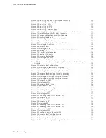
Figure 22: System Architecture . . . . . . . . . . . . . . . . . . . . . . . . . . . . . . . . . . . . . . . . . . . . . . . . . . . . . . . . . . . . . . . . . 51
Figure 23: Packet Forwarding Engine Components and Data Flow . . . . . . . . . . . . . . . . . . . . . . . . . . . 53
Figure 24: Routing Engine Architecture . . . . . . . . . . . . . . . . . . . . . . . . . . . . . . . . . . . . . . . . . . . . . . . . . . . . . . . . 54
Figure 25: Control Packet Handling for Routing and Forwarding Table Updates . . . . . . . . . . . . . 55
Figure 26: Typical Center-Mount Rack. . . . . . . . . . . . . . . . . . . . . . . . . . . . . . . . . . . . . . . . . . . . . . . . . . . . . . . . . . 61
Figure 27: Chassis Dimensions and Clearance Requirements. . . . . . . . . . . . . . . . . . . . . . . . . . . . . . . . . 62
Figure 28: Power and Grounding Cable Lug . . . . . . . . . . . . . . . . . . . . . . . . . . . . . . . . . . . . . . . . . . . . . . . . . . . . 67
Figure 29: Typical Source Cabling to the Router . . . . . . . . . . . . . . . . . . . . . . . . . . . . . . . . . . . . . . . . . . . . . . . 68
Figure 30: Power and Grounding Cable Connections . . . . . . . . . . . . . . . . . . . . . . . . . . . . . . . . . . . . . . . . . . 70
Figure 31: Unpacking the Router . . . . . . . . . . . . . . . . . . . . . . . . . . . . . . . . . . . . . . . . . . . . . . . . . . . . . . . . . . . . . . . 79
Figure 32: Removing a Power Supply . . . . . . . . . . . . . . . . . . . . . . . . . . . . . . . . . . . . . . . . . . . . . . . . . . . . . . . . . . 86
Figure 33: Removing an SFM . . . . . . . . . . . . . . . . . . . . . . . . . . . . . . . . . . . . . . . . . . . . . . . . . . . . . . . . . . . . . . . . . . . 88
Figure 34: Removing an MCS . . . . . . . . . . . . . . . . . . . . . . . . . . . . . . . . . . . . . . . . . . . . . . . . . . . . . . . . . . . . . . . . . . . 89
Figure 35: Removing a PCG . . . . . . . . . . . . . . . . . . . . . . . . . . . . . . . . . . . . . . . . . . . . . . . . . . . . . . . . . . . . . . . . . . . . . 90
Figure 36: Removing a Routing Engine. . . . . . . . . . . . . . . . . . . . . . . . . . . . . . . . . . . . . . . . . . . . . . . . . . . . . . . . . 91
Figure 37: Removing the Rear Upper Impeller Assembly . . . . . . . . . . . . . . . . . . . . . . . . . . . . . . . . . . . . . 92
Figure 38: Removing the Rear Upper Impeller Assembly . . . . . . . . . . . . . . . . . . . . . . . . . . . . . . . . . . . . . 92
Figure 39: Removing the Rear Lower Impeller Assembly . . . . . . . . . . . . . . . . . . . . . . . . . . . . . . . . . . . . . 93
Figure 40: Removing the Fan Tray . . . . . . . . . . . . . . . . . . . . . . . . . . . . . . . . . . . . . . . . . . . . . . . . . . . . . . . . . . . . . . 94
Figure 41: Removing an FPC . . . . . . . . . . . . . . . . . . . . . . . . . . . . . . . . . . . . . . . . . . . . . . . . . . . . . . . . . . . . . . . . . . . . 96
Figure 42: Removing the Front Impeller Assembly . . . . . . . . . . . . . . . . . . . . . . . . . . . . . . . . . . . . . . . . . . . . 97
Figure 43: Attaching the Lifting Handle . . . . . . . . . . . . . . . . . . . . . . . . . . . . . . . . . . . . . . . . . . . . . . . . . . . . . . . . 98
Figure 44: Installing the Chassis in a Rack . . . . . . . . . . . . . . . . . . . . . . . . . . . . . . . . . . . . . . . . . . . . . . . . . . . . . 99
Figure 45: Reinstalling the Front Impeller Assembly . . . . . . . . . . . . . . . . . . . . . . . . . . . . . . . . . . . . . . . . . 101
Figure 46: Reinstalling an FPC . . . . . . . . . . . . . . . . . . . . . . . . . . . . . . . . . . . . . . . . . . . . . . . . . . . . . . . . . . . . . . . . . 102
Figure 47: Reinstalling the Fan Tray . . . . . . . . . . . . . . . . . . . . . . . . . . . . . . . . . . . . . . . . . . . . . . . . . . . . . . . . . . . 103
Figure 48: Reinstalling the Rear Lower Impeller Assembly. . . . . . . . . . . . . . . . . . . . . . . . . . . . . . . . . . . 104
Figure 49: Reinstalling the Rear Upper Impeller Assembly. . . . . . . . . . . . . . . . . . . . . . . . . . . . . . . . . . . 105
List of Figures
xiii
Содержание Internet Router M160
Страница 12: ...M160 Internet Router Hardware Guide xii Table of Contents ...
Страница 16: ...M160 Internet Router Hardware Guide xvi List of Figures ...
Страница 18: ...M160 Internet Router Hardware Guide xviii List of Tables ...
Страница 24: ...M160 Internet Router Hardware Guide xxiv Requesting Support ...
Страница 26: ...2 Product Overview ...
Страница 30: ...M160 Internet Router Hardware Guide 6 Safety Requirements Warnings and Guidelines ...
Страница 66: ...M160 Internet Router Hardware Guide 42 Cable Management System ...
Страница 80: ...M160 Internet Router Hardware Guide 56 Routing Engine Architecture ...
Страница 82: ...58 Initial Installation ...
Страница 104: ...M160 Internet Router Hardware Guide 80 Unpacking the Router ...
Страница 148: ...M160 Internet Router Hardware Guide 124 Configuring the JUNOS Internet Software ...
Страница 150: ...126 Hardware Maintenance Replacement and Troubleshooting Procedures ...
Страница 242: ...M160 Internet Router Hardware Guide 218 Troubleshooting the Power System ...
Страница 244: ...220 Appendixes ...
Страница 292: ...M160 Internet Router Hardware Guide 268 Packing Components for Shipment ...
Страница 301: ...Part 5 Index Index 277 ...
Страница 302: ...278 Index ...


