M160 Internet Router Hardware Guide
Figure 50: Reinstalling the Rear Upper Impeller Assembly. . . . . . . . . . . . . . . . . . . . . . . . . . . . . . . . . . . 105
Figure 51: Reinstalling a Routing Engine . . . . . . . . . . . . . . . . . . . . . . . . . . . . . . . . . . . . . . . . . . . . . . . . . . . . . . 106
Figure 52: Reinstalling a PCG . . . . . . . . . . . . . . . . . . . . . . . . . . . . . . . . . . . . . . . . . . . . . . . . . . . . . . . . . . . . . . . . . . 107
Figure 53: Reinstalling an MCS . . . . . . . . . . . . . . . . . . . . . . . . . . . . . . . . . . . . . . . . . . . . . . . . . . . . . . . . . . . . . . . . 108
Figure 54: Reinstalling an SFM. . . . . . . . . . . . . . . . . . . . . . . . . . . . . . . . . . . . . . . . . . . . . . . . . . . . . . . . . . . . . . . . . 109
Figure 55: Reinstalling a Power Supply . . . . . . . . . . . . . . . . . . . . . . . . . . . . . . . . . . . . . . . . . . . . . . . . . . . . . . . . 110
Figure 56: Routing Engine Management Ports and Alarm Relay Contacts . . . . . . . . . . . . . . . . . . 113
Figure 57: Routing Engine Ethernet Cable Connector . . . . . . . . . . . . . . . . . . . . . . . . . . . . . . . . . . . . . . . . 114
Figure 58: Console and Auxiliary Serial Port Connector . . . . . . . . . . . . . . . . . . . . . . . . . . . . . . . . . . . . . . 115
Figure 59: Attaching Cable to a PIC. . . . . . . . . . . . . . . . . . . . . . . . . . . . . . . . . . . . . . . . . . . . . . . . . . . . . . . . . . . . 117
Figure 60: Connecting Power and Grounding Cables . . . . . . . . . . . . . . . . . . . . . . . . . . . . . . . . . . . . . . . . . 119
Figure 61: Removing the Air Filter . . . . . . . . . . . . . . . . . . . . . . . . . . . . . . . . . . . . . . . . . . . . . . . . . . . . . . . . . . . . .129
Figure 62: Removing the Filter from the Air Filter Cover . . . . . . . . . . . . . . . . . . . . . . . . . . . . . . . . . . . . .129
Figure 63: Installing the Air Filter . . . . . . . . . . . . . . . . . . . . . . . . . . . . . . . . . . . . . . . . . . . . . . . . . . . . . . . . . . . . . .130
Figure 64: Removing the CIP . . . . . . . . . . . . . . . . . . . . . . . . . . . . . . . . . . . . . . . . . . . . . . . . . . . . . . . . . . . . . . . . . .143
Figure 65: Installing the CIP. . . . . . . . . . . . . . . . . . . . . . . . . . . . . . . . . . . . . . . . . . . . . . . . . . . . . . . . . . . . . . . . . . . .144
Figure 66: Routing Engine Interface Ports and Alarm Relay Contacts . . . . . . . . . . . . . . . . . . . . . . .145
Figure 67: Ethernet Cable Connector . . . . . . . . . . . . . . . . . . . . . . . . . . . . . . . . . . . . . . . . . . . . . . . . . . . . . . . . . .146
Figure 68: Serial Port Connector . . . . . . . . . . . . . . . . . . . . . . . . . . . . . . . . . . . . . . . . . . . . . . . . . . . . . . . . . . . . . . .147
Figure 69: Removing the Fan Tray . . . . . . . . . . . . . . . . . . . . . . . . . . . . . . . . . . . . . . . . . . . . . . . . . . . . . . . . . . . . .149
Figure 70: Installing the Fan Tray . . . . . . . . . . . . . . . . . . . . . . . . . . . . . . . . . . . . . . . . . . . . . . . . . . . . . . . . . . . . . .150
Figure 71: Removing the Front Impeller Assembly . . . . . . . . . . . . . . . . . . . . . . . . . . . . . . . . . . . . . . . . . . .152
Figure 72: Removing the Screws along the Top Front Edge of the Front Impeller
Assembly. . . . . . . . . . . . . . . . . . . . . . . . . . . . . . . . . . . . . . . . . . . . . . . . . . . . . . . . . . . . . . . . . . . . . . . . . . . . . . . . . . .153
Figure 73: Removing the Craft Interface . . . . . . . . . . . . . . . . . . . . . . . . . . . . . . . . . . . . . . . . . . . . . . . . . . . . . .153
Figure 74: Installing the Front Impeller Assembly . . . . . . . . . . . . . . . . . . . . . . . . . . . . . . . . . . . . . . . . . . . .154
Figure 75: Removing the Rear Lower Impeller Assembly . . . . . . . . . . . . . . . . . . . . . . . . . . . . . . . . . . . .155
Figure 76: Installing the Rear Lower Impeller Assembly . . . . . . . . . . . . . . . . . . . . . . . . . . . . . . . . . . . . .156
Figure 77: Removing the Rear Upper Impeller Assembly . . . . . . . . . . . . . . . . . . . . . . . . . . . . . . . . . . . .157
Figure 78: Removing the Rear Upper Impeller Assembly . . . . . . . . . . . . . . . . . . . . . . . . . . . . . . . . . . . .158
Figure 79: Installing the Rear Upper Impeller Assembly . . . . . . . . . . . . . . . . . . . . . . . . . . . . . . . . . . . . .158
Figure 80: Installing the Rear Upper Impeller Assembly . . . . . . . . . . . . . . . . . . . . . . . . . . . . . . . . . . . . .159
Figure 81: Removing an MCS . . . . . . . . . . . . . . . . . . . . . . . . . . . . . . . . . . . . . . . . . . . . . . . . . . . . . . . . . . . . . . . . . . 161
Figure 82: Installing an MCS . . . . . . . . . . . . . . . . . . . . . . . . . . . . . . . . . . . . . . . . . . . . . . . . . . . . . . . . . . . . . . . . . . .162
Figure 83: Removing the PC Card . . . . . . . . . . . . . . . . . . . . . . . . . . . . . . . . . . . . . . . . . . . . . . . . . . . . . . . . . . . . .164
Figure 84: Insert the PC Card . . . . . . . . . . . . . . . . . . . . . . . . . . . . . . . . . . . . . . . . . . . . . . . . . . . . . . . . . . . . . . . . . .165
Figure 85: Removing a Routing Engine. . . . . . . . . . . . . . . . . . . . . . . . . . . . . . . . . . . . . . . . . . . . . . . . . . . . . . . .167
Figure 86: Installing a Routing Engine. . . . . . . . . . . . . . . . . . . . . . . . . . . . . . . . . . . . . . . . . . . . . . . . . . . . . . . . .169
Figure 87: Removing an FPC. . . . . . . . . . . . . . . . . . . . . . . . . . . . . . . . . . . . . . . . . . . . . . . . . . . . . . . . . . . . . . . . . . .172
Figure 88: Installing an FPC . . . . . . . . . . . . . . . . . . . . . . . . . . . . . . . . . . . . . . . . . . . . . . . . . . . . . . . . . . . . . . . . . . . .175
Figure 89: Connecting Fiber-Optic Cable to a PIC . . . . . . . . . . . . . . . . . . . . . . . . . . . . . . . . . . . . . . . . . . . .176
Figure 90: Removing a PCG . . . . . . . . . . . . . . . . . . . . . . . . . . . . . . . . . . . . . . . . . . . . . . . . . . . . . . . . . . . . . . . . . . . .177
Figure 91: Installing a PCG . . . . . . . . . . . . . . . . . . . . . . . . . . . . . . . . . . . . . . . . . . . . . . . . . . . . . . . . . . . . . . . . . . . . .179
Figure 92: Removing a PIC. . . . . . . . . . . . . . . . . . . . . . . . . . . . . . . . . . . . . . . . . . . . . . . . . . . . . . . . . . . . . . . . . . . . . 181
Figure 93: Installing a PIC . . . . . . . . . . . . . . . . . . . . . . . . . . . . . . . . . . . . . . . . . . . . . . . . . . . . . . . . . . . . . . . . . . . . . .184
Figure 94: Connecting Fiber-Optic Cable to a PIC . . . . . . . . . . . . . . . . . . . . . . . . . . . . . . . . . . . . . . . . . . . .184
Figure 95: Connecting Fiber-Optic Cable to a PIC . . . . . . . . . . . . . . . . . . . . . . . . . . . . . . . . . . . . . . . . . . . .187
Figure 96: Removing an SFM . . . . . . . . . . . . . . . . . . . . . . . . . . . . . . . . . . . . . . . . . . . . . . . . . . . . . . . . . . . . . . . . . .189
Figure 97: Installing an SFM . . . . . . . . . . . . . . . . . . . . . . . . . . . . . . . . . . . . . . . . . . . . . . . . . . . . . . . . . . . . . . . . . . .190
Figure 98: Small Form Factor Pluggable (SFP) . . . . . . . . . . . . . . . . . . . . . . . . . . . . . . . . . . . . . . . . . . . . . . . .190
Figure 99: Removing the Circuit Breaker Box . . . . . . . . . . . . . . . . . . . . . . . . . . . . . . . . . . . . . . . . . . . . . . . . .195
Figure 100: Installing the Circuit Breaker Box . . . . . . . . . . . . . . . . . . . . . . . . . . . . . . . . . . . . . . . . . . . . . . . . .197
Figure 101: Removing a Power Supply . . . . . . . . . . . . . . . . . . . . . . . . . . . . . . . . . . . . . . . . . . . . . . . . . . . . . . . .198
Figure 102: Rear of Power Supply Showing Midplane Connectors . . . . . . . . . . . . . . . . . . . . . . . . . . .199
xiv
List of Figures
Содержание Internet Router M160
Страница 12: ...M160 Internet Router Hardware Guide xii Table of Contents ...
Страница 16: ...M160 Internet Router Hardware Guide xvi List of Figures ...
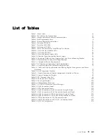
Страница 18: ...M160 Internet Router Hardware Guide xviii List of Tables ...
Страница 24: ...M160 Internet Router Hardware Guide xxiv Requesting Support ...
Страница 26: ...2 Product Overview ...
Страница 30: ...M160 Internet Router Hardware Guide 6 Safety Requirements Warnings and Guidelines ...
Страница 66: ...M160 Internet Router Hardware Guide 42 Cable Management System ...
Страница 80: ...M160 Internet Router Hardware Guide 56 Routing Engine Architecture ...
Страница 82: ...58 Initial Installation ...
Страница 104: ...M160 Internet Router Hardware Guide 80 Unpacking the Router ...
Страница 148: ...M160 Internet Router Hardware Guide 124 Configuring the JUNOS Internet Software ...
Страница 150: ...126 Hardware Maintenance Replacement and Troubleshooting Procedures ...
Страница 242: ...M160 Internet Router Hardware Guide 218 Troubleshooting the Power System ...
Страница 244: ...220 Appendixes ...
Страница 292: ...M160 Internet Router Hardware Guide 268 Packing Components for Shipment ...
Страница 301: ...Part 5 Index Index 277 ...
Страница 302: ...278 Index ...


