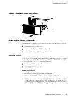
Replacing Hardware Components
is attached to a proper earth ground. For more information about ESD, see
“Preventing Electrostatic Discharge Damage” on page 226.
2.
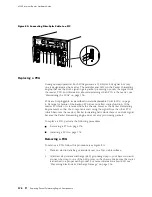
Verify that the ends of the ejector levers, which are located at each end of the
FPC, are pushed outward, nearly perpendicular to the face of the FPC.
3.
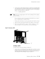
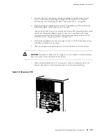
Grasp the front of the FPC with one hand and place the other hand under
the FPC to support it.
CAUTION:
When the FPC is out of the chassis, do not hold it by the ejector levers,
bus bars, or edge connectors. They cannot support its weight.
4.
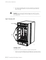
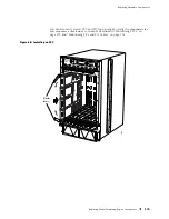
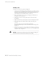
Align the rear bottom corners of the FPC with the guides at the bottom of the
FPC slot. Slide the FPC into the card cage until it contacts the midplane.
5.
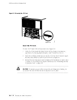
Push the ends of the ejector levers inward until they are nearly flush with
the face of the FPC.
6.
Tighten the thumbscrew at each end of the FPC to seat the FPC securely
in the chassis.
7.
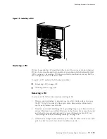
If you are installing different PICs in the FPC, follow this procedure for each one:
a.
If the PIC uses fiber-optic cable, verify that there is a rubber safety cap over
each transceiver on the faceplate. Install a cap if necessary.
b.
Slide the PIC into a slot in the FPC, aligning the notches in the connector
at the rear of the PIC with the notches in the FPC slot and then firmly
pushing the PIC into place.
CAUTION:
Insert the PIC straight into the FPC slot to avoid damaging the
components on the bottom of the PIC.
c.
Tighten the thumbscrews at the ends of the PIC faceplate simultaneously
and at about the same rate (tightening the two screws alternately or at very
different rates can cause the PIC to become lodged in the FPC slot, making
it difficult to turn the screws). Verify that the PIC is seated properly.
8.
If any of the PICs on the FPC connect to fiber-optic cable, remove the rubber
safety cap from each transceiver and cable.
WARNING:
Do not look directly into the ends of fiber-optic cables or into the
transceivers on the interface faceplate. Single-mode fiber-optic cable and the
Replacing Packet Forwarding Engine Components
173
Содержание Internet Router M160
Страница 12: ...M160 Internet Router Hardware Guide xii Table of Contents ...
Страница 16: ...M160 Internet Router Hardware Guide xvi List of Figures ...
Страница 18: ...M160 Internet Router Hardware Guide xviii List of Tables ...
Страница 24: ...M160 Internet Router Hardware Guide xxiv Requesting Support ...
Страница 26: ...2 Product Overview ...
Страница 30: ...M160 Internet Router Hardware Guide 6 Safety Requirements Warnings and Guidelines ...
Страница 66: ...M160 Internet Router Hardware Guide 42 Cable Management System ...
Страница 80: ...M160 Internet Router Hardware Guide 56 Routing Engine Architecture ...
Страница 82: ...58 Initial Installation ...
Страница 104: ...M160 Internet Router Hardware Guide 80 Unpacking the Router ...
Страница 148: ...M160 Internet Router Hardware Guide 124 Configuring the JUNOS Internet Software ...
Страница 150: ...126 Hardware Maintenance Replacement and Troubleshooting Procedures ...
Страница 242: ...M160 Internet Router Hardware Guide 218 Troubleshooting the Power System ...
Страница 244: ...220 Appendixes ...
Страница 292: ...M160 Internet Router Hardware Guide 268 Packing Components for Shipment ...
Страница 301: ...Part 5 Index Index 277 ...
Страница 302: ...278 Index ...

