


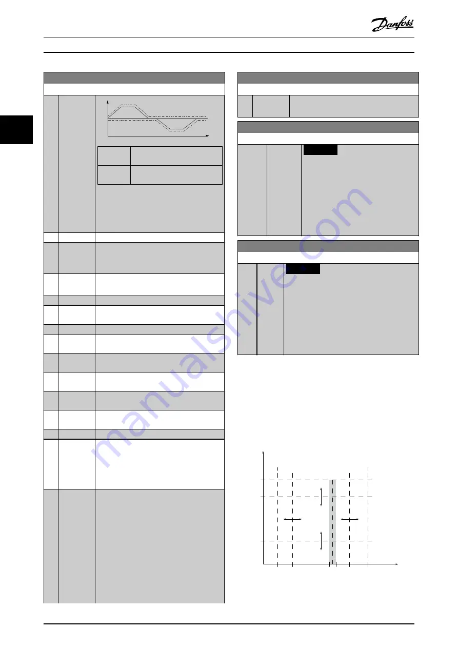
4-43 Motor Speed Monitor Function
Option:
Function:
Speed
nRef
-nRef
0rpm
Time
130BE199.10
Solid line
Parameter 16-48 Speed Ref. After
Ramp [RPM]
Dotted
line
Parameter 4-44 Motor Speed
Monitor Max
Illustration 3.32 Speed Reference and
Maximum Allowed Speed Difference
[0]
Disabled
[1]
Warning
The frequency converter reports
warning 101,
Speed monitor
when the speed is outside the
limit.
[2]
Trip
The frequency converter trips and reports
alarm 101, Speed monitor
.
[3]
Jog
[4]
Freeze
Output
[5]
Max Speed
[6]
Switch to
Open Loop
[7]
Select
Setup 1
[8]
Select
Setup 2
[9]
Select
Setup 3
[10] Select
Setup 4
[11] Stop & Trip
[12] Trip/
Warning
The frequency converter reports
alarm 101,
Speed monitor
in running mode and
warning
101, Speed monitor
in stop or coast mode. This
option is only available in closed-loop
operation.
[13] Trip/Catch
Select when there is a need to catch a load,
for example when mechanical braking fails.
This option is available in closed loop only.
The frequency converter trips and reports
alarm 101, Speed monitor
in running mode. In
stop mode, the frequency converter catches
the flying load and reports
warning 101, Speed
monitor
.
In catch mode, the frequency converter
applies holding torque to control the 0 speed
on a potentially malfunctioning brake (closed
loop). To exit this mode, send a new start
4-43 Motor Speed Monitor Function
Option:
Function:
signal to the frequency converter. A coast or
Safe Torque Off also terminates the function.
4-44 Motor Speed Monitor Max
Range:
Function:
300
RPM
*
[10 - 500
RPM]
NOTICE
Only available in flux control
principle.
Enter the maximum allowable speed
deviation between the actual mechanical
shaft speed and the value in
parameter 16-48 Speed Ref. After Ramp
[RPM]
4-45 Motor Speed Monitor Timeout
Range:
Function:
0.1 s
*
[0 - 60
s]
NOTICE
Only available in flux control principle.
Enter the timeout period during which a
deviation defined in
is allowable. The timer for this
parameter is reset if the deviation stops
exceeding the value in
.
3.5.4 4-5* Adjustable Warnings
Use these parameters to adjust warning limits for current,
speed, reference, and feedback.
Warnings are shown on the LCP and can be programmed
to be outputs or to be read out via fieldbus in the
extended status word.
130BA064.10
(P 4-18)
(P 4-51)
(P 4-50)
(P 4-11)
(P 4-53)
(P 4-52)
(P 4-13)
I
HIGH
I
LOW
n
LOW
n
HIGH
n
motor
I
motor
REF
ON REF
IN RANGE
I
LIM
n
MAX
n
MIN
[RPM]
Illustration 3.33 Adjustable Warnings
Parameter Descriptions
VLT
®
AutomationDrive FC 301/302
92
Danfoss A/S © 10/2018 All rights reserved.
MG33MP02
3
3
Содержание VLT AutomationDrive FC 302
Страница 2: ......