


7
−
82
62-11389
Alarm
NO.
Steps
Alarm/Cause
Corrective Action
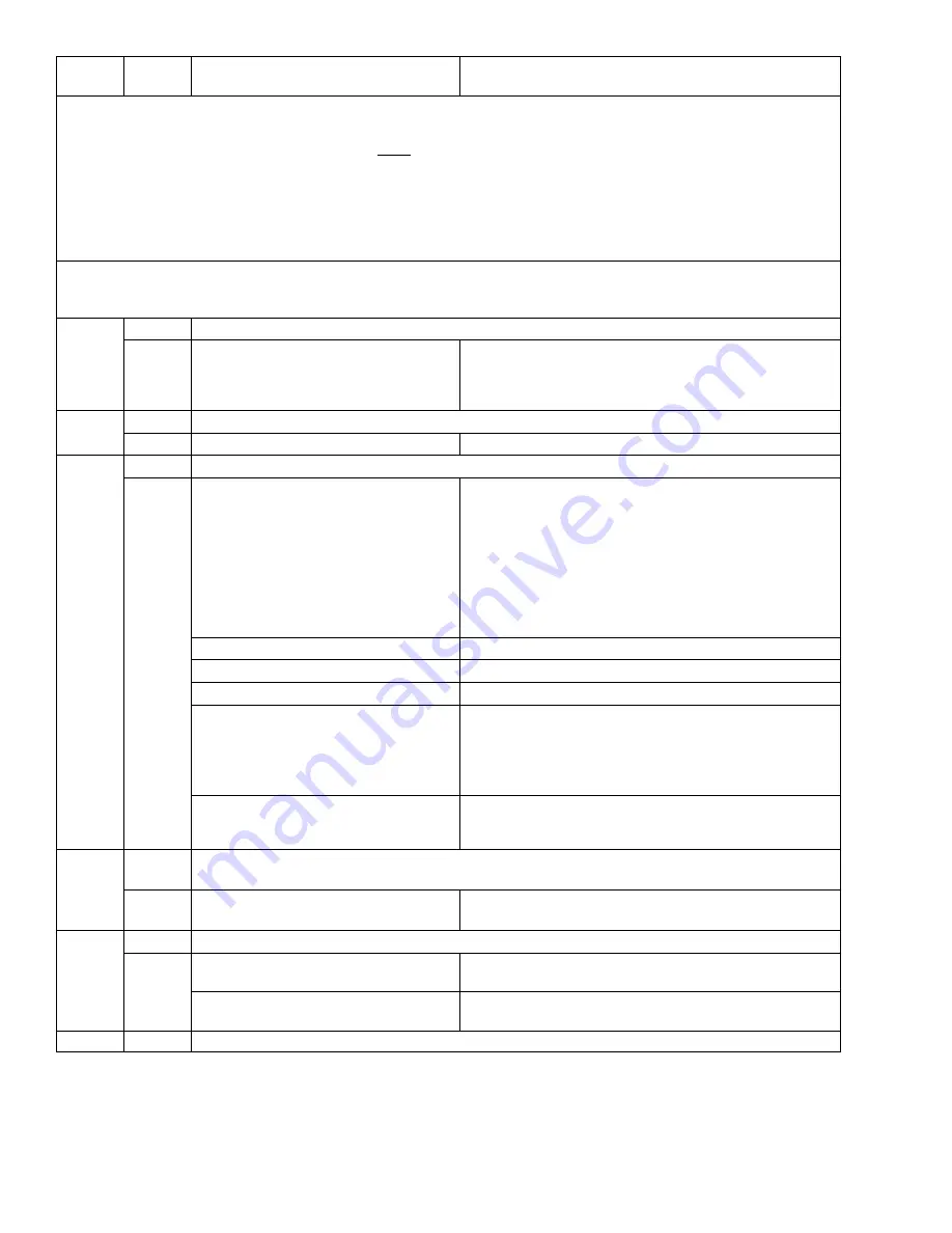
P175 CHECK HIGH SPEED RPM
•
TRIGGER–ON: With Speed Relay energized (voltage at the Engine Speed Control Unit for high
speed operation), engine RPM is NOT between 1700 and 1900.
•
UNIT CONTROL:
Engine Operation: Pretrip will fail and display
“PRETRIP FAIL AND COMPLETED”.
Standby Operation: This test is not made.
•
RESET CONDITION: Auto Reset if Pretrip is started again, or Alarm may be manually reset via
Keypad or by turning the unit off, then back on again.
NOTE: Follow the steps below until a problem is found. Once a repair or correction has been made, clear the
alarm(s). (See Note 1 page 7
−
2.) Operate the unit through the appropriate modes to see if any active alarm
occurs. Continue with the steps below as necessary.
1
Check Model Number
Verify that the model number on the
nameplate matches the model num-
ber shown in the microprocessor Un-
it Data.
Enter the correct number in the data list. (Refer to
Section 3.13.)
2
Check the fuel/speed actuator
Check FSA plunger.
Must move in and out freely.
3
Force high speed operation (See Note 5 page 7
−
2)
a. Set Functional Parameter “LOW
SPEED START” to zero and adjust
set point at least 10
°
F (5.6
°
C)
above or below refrigerated com-
partment temperature then start the
unit.
Set Functional Parameter back
to original setting after complet-
ing repairs.
LED 27 must be ON.
b. Check operation of Speed Relay.
LED 27 must be ON.
c. Check voltage to FSA.
Must be 12-14 VDC.
d. Check resistance of FSA.
Refer to Section 2.12 for correct electrical values.
e. Check amp draw of FSA.
Use Component Test Mode to energize the Speed
Relay circuit. (Section 5.2.2.)
Refer to Section 2.12 for correct electrical values.
View current draw in the Unit Data. (Refer to Section
3.13.
f. Inspect harness & control box
connector pins & terminals. (See
wiring schematic Section 10.)
No physical damage to harness.
No damage, moisture, or corrosion in connectors.
4
Check for proper voltage to the Engine Speed Control Unit (ENSCU) Pin 16 Based On
Requested Speed From The Microprocessor
Check 12 VDC at pin 16 with unit
running.
Must be 12 VDC when the microprocessor is calling
for high speed.
5
Check engine RPM
a. Check actual engine RPM using
hand held tachometer.
Check Speed Control System, refer to Section 9.5
b. Compare actual RPM with those
shown on display.
Both readings within
±
50 RPM.
Additional steps on the next page.


