


●
In CCD basic mode or CCD system mode, the error number can be se‐
lectively configured in the AT (drive telegram) in order to exclude specif‐
ic axes from automatic error generation.
With MLD-M, the remote axes have to be taken into account in
addition to how the local axis handles errors.
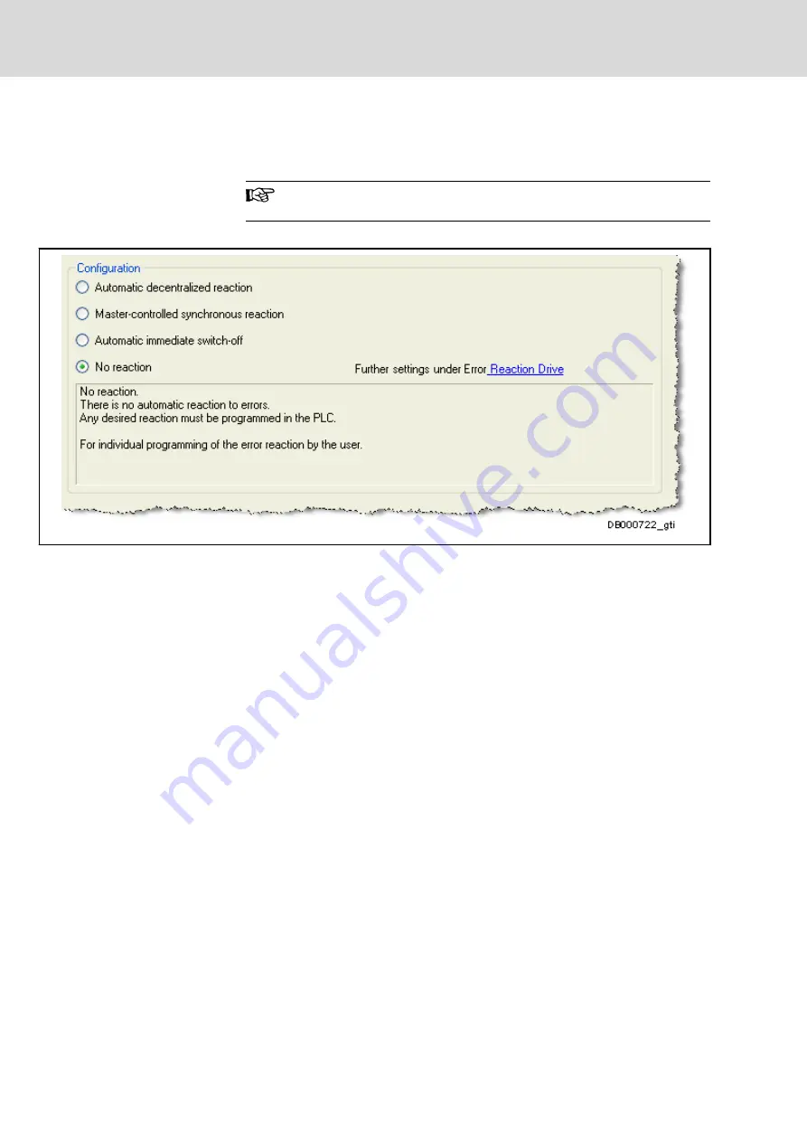
Configuring in IndraWorks
The error reaction is configured via the following IndraWorks dialog:
Fig. 4-29:
IndraWorks dialog: CCD/MLD error reaction
Configuring via direct parameter
access
Independent of the dialog, it is also possible to directly edit parameter
"P-0-1367, PLC configuration" and use bit 7 "deactivate function block error
reaction" to select the reaction to a commanding error:
●
Bit7="0": Function block commanding errors are ignored
●
Bit7="1": Function block commanding errors are handled according to
the table below
Bosch Rexroth AG
DOK-INDRV*-MLD3-**VRS*-AP02-EN-P
80/267
Rexroth IndraDrive Rexroth IndraMotion MLD (2G) as of MPx-18
Basic functions of Rexroth IndraMotion MLD
LSA Control S.L. www.lsa-control.com [email protected] (+34) 960 62 43 01