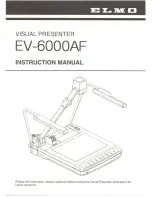
3. Set the threshold.
a) Expand the Threshold parameters.
b) Move the sliders
until
the edge of the needle is found with few extra points included.
Figure 176. Good Part
4. Set the edge polarity.
a) Expand the Edge Polarity parameters.
b) Select Bright to Dark because the needle is dark against a light background.
5. Set the Test parameters to set the pass/fail criteria.
a) On the Test tab, select the Length checkbox to enable the test parameter.
This
option
sets the minimum and maximum length so that a part passes.
b) Expand Length and move the sliders to set the acceptable length range.
c) Select the Angle checkbox to enable the test parameter.
This
option
sets the minimum and maximum angle of the part.
d) Move the slider or enter the angle range to ensure that only straight parts pass.
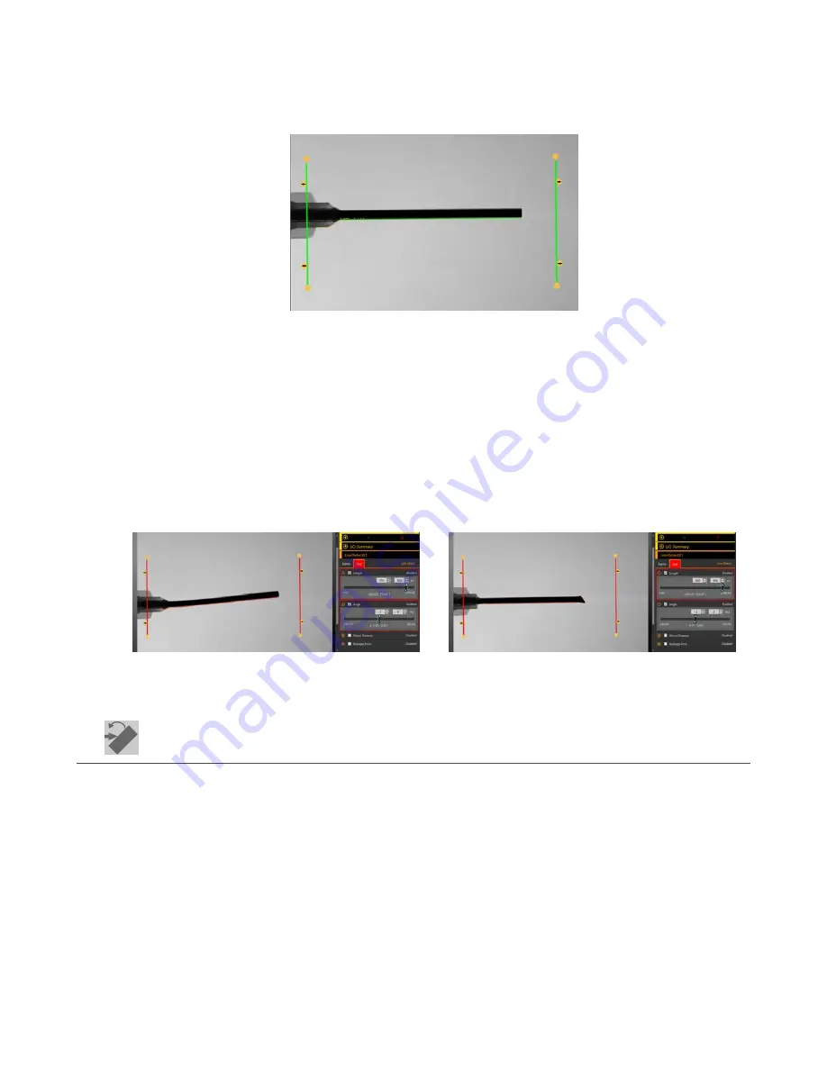
6. Test a complete range of good and bad samples to make sure that the sensor accepts good parts and rejects bad parts.
Figure 177. Bad Part—Bent Needle
Figure 178. Bad Part—Deformed Needle
8.8
Locate Tool
Use the Locate tool to
find
the edge of a part and to compensate for
translation
and
rotation
(if selected).
This tool
finds
and marks the
position
of the
first
edge along the ROI line and aligns and
positions
related tools consistently over a
feature of interest. When
Rotation
is enabled, the Locate tool calculates the angle at which the tool intersects the feature's edge and
rotates the Regions of Interest (ROIs) of downstream tools accordingly.
When a Locate tool is added to an
inspection,
the
inspection
fails and there is a red box around Use as Reference. This is because a
reference point has not yet been set.
Configure
the Locate tool as desired, and then set the reference point.
Example
application:
Adjust
inspection
tools for a part that moves and/or rotates in the FOV.
VE Series Smart Camera
100
www.bannerengineering.com - Tel: 763.544.3164