2 Overview
The VE Series Smart Camera is easy to use and has advanced visual
inspection
capabilities
for
automation
or control
applications.
Users
can quickly set up the sensor using the Vision Manager
software
to solve a diverse range of
applications
on the factory
floor.
2.1 Features
1
2
3
4
5
7
6
8
9
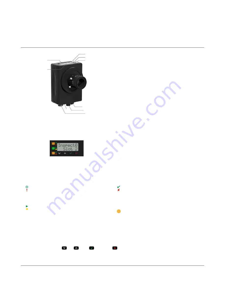
Figure 1. Sensor Features
1. Display
2.
Buttons
3. Pass/Fail indicator (green/red)
4. Ready/Trigger indicator (green/amber)
5. Power/Error indicator (green/red)
6. Ethernet indicator (amber), not shown
7. Ethernet
connection
8. Light
connection
9. Power, Discrete I/O
connection
2.1.1 Display
Figure 2. Display with Home Screen
The display is a 2-line, 8-character LCD. The main screen is the
Home Screen, which shows the name of the current
inspection
and the slot number
(inspection
location).
Use the display to view
or change several sensor
settings.
2.1.2 Indicators
Four LED indicators provide ongoing
indication
of the sensing status.
Power/Error Indicator
Green = Normal
operation
Red = System error
Ready/Trigger Indicator
Green = Ready for trigger
Yellow = Trigger is
active
OFF = Not ready for a trigger, triggers will be missed
Pass/Fail Indicator
Green = Previous
inspection
passed
Red = Previous
inspection
failed
OFF = No trigger since power up
Ethernet Indicator
Amber solid = Ethernet
connection
Amber
flashing
= Ethernet
activity
OFF = no
connection
2.1.3
Buttons
Use the sensor
buttons
Down
, Up
, Enter
, and Escape
to
configure
several sensor
settings
and to access sensor
information.
on page 143 for
additional
information
on using the
buttons.
2.2 Vision Manager
Software
Set up the VE Series Smart Camera using the free Vision Manager
Software,
available for download at
VE Series Smart Camera
www.bannerengineering.com - Tel: 763.544.3164
7


