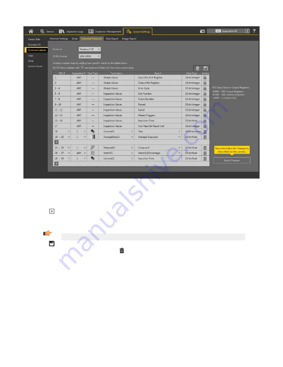
Figure 326. Industrial Protocols Tab—Modbus/TCP
The results are
configurable
only for the current
inspection.
However, all
user-defined
results in the custom map are shown on the
Industrial Protocols tab whether or not they are included in the current
inspection.
To make changes to a
different
inspection,
switch to
the desired
inspection
and then make changes to the custom map.
Updating
the map does not disconnect the sensor from the PLC.
To
configure
the map:
1. Click
to add a new line to the map.
2. Set the Word/Register/Byte, Tool Name, and Result. See the following
descriptions
for more
information.
3. Click Apply Changes to send the current map to the camera.
Important: Click Apply Changes or all
user-defined
data is lost when you click away from the Industrial Protocols tab.
4. Click
to print and save a PDF of the current map. The PDF includes all data, whether
system-defined
or
user-defined.
5. To return the map to the default
settings,
click . All
user-defined
output data is deleted.
Column
descriptions:
REG #
The data
location.
Inspection
#
Shows whether this tool result applies to the current
inspection
only (
inspection
number) or to any
inspection
(ANY) that
includes the selected tool.
An
Inspection
# of ANY means that if an
inspection
includes a tool with the exact name (for example, AverageGray01), the
results are output. If an
inspection
does not have a tool with the exact name (for example AverageGrayAssemblyLine01), no
results are output for that tool and that
inspection.
Tool Type
Displays a graphic that represents the type of tool selected in the Tool Name column.
Tool Name
Select the desired Tool Name from the list. The list includes the tools available in the current
inspection
only. Select a
different
inspection
from the
inspection
list, if necessary.
VE Series Smart Camera
www.bannerengineering.com - Tel: 763.544.3164
181