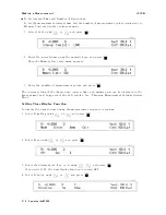


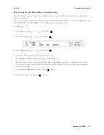


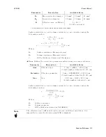
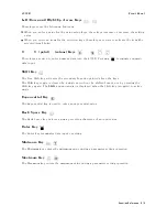


Front
P
anel
4339B
Front
P
anel
Figure
3-1.
Front
P
anel
Note
In
this
manual,
the
blue
shift
key
is
expressed
as
,
even
though
the
top
of
the
key
is
not
labeled
with
the
word
\blue".
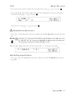
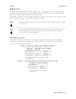
Display
The
display
serves
two
functions
|
character
display
and
annunciator
display
.
The
character
display
shows
the
measurement
result,
instrument
setting
information,
and
instrument
messages
.
The
4339B
has
four
measurement
display
modes
.
F
or
details
about
the
display
modes
,
refer
to
\Display
Mode
Key
".
Some
of
the
instrument's
current
settings
are
displayed
in
the
Measurement
Settings
area.
The
annunciator
(
9
)
points
to
the
currently
selected
instrument
settings
.
The
annunciator
labels
are
as
follows:
Seq
Running
(Sequence
Running)
Indicates
the
measurement
sequence
is
running.
Meas
Time
(Measurement
Time)
Indicates
measurement
time
mode
|
Short,
Medium,
or
Long.
Trigger
Indicates
the
trigger
mode
setting:
Internal
(Int ),
Manual
(Man ),
or
External
(Ext ).
Hold
Range
Indicates
the
measurement
range
mode
.
when
this
annunciator
is
not
lit,
the
4339B
is
in
the
A
uto
range
mode
.
Comprtr
On
(Comparator
On)
Indicates
the
comparator
function
is
ON.
Cont
Chk
(Contact
Check
On)
Indicates
the
contact
check
function
is
ON.
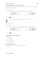
T
alk
Only
(A
ddressed)
Indicates
that
the
4339B
is
in
the
T
alk
Only
mode
.
Rmt
(Remote)
Indicates
that
the
4339B
is
in
the
GPIB
remote
mode
or
the
talk
only
mode
.
K
ey
Lock
Indicates
the
4339B's
front
panel
keys
are
locked
out.
Shift
Indicates
that
the
is
pressed.
(Shift
is
active
.)
3-2
Function
Reference
Содержание 4339B
Страница 10: ......
Страница 18: ... ᄌᦝ 0123 45 6789 8 A B C ᄌᦝ 3 DE FG H FG IJ B C K 9 C Copyright 2007 Agilent Technologies ...
Страница 20: ......
Страница 21: ......
Страница 22: ......
Страница 24: ......
Страница 25: ......
Страница 26: ......
Страница 30: ......
Страница 44: ......
Страница 55: ...4339B Initial Inspection Figure 1 1 Power Cable Supplied Getting Started 1 11 ...
Страница 212: ......
Страница 220: ......
Страница 230: ......
Страница 256: ......
Страница 262: ...4339B Figure B 1 Handler Interface Comparison Output Signals Diagram B 2 Handler Interface Installation ...
Страница 263: ...4339B Figure B 2 Handler Interface Control Output Signals Diagram Handler Interface Installation B 3 ...
Страница 268: ...Procedure 4339B Figure B 5 A1 Main Board B 8 Handler Interface Installation ...


