


4339B
Procedure
5.
Remove
the
A1
board
assembly
.
a.
Disconnect
the
following
cable
assemblies
from
the
A1
board.
i.
F
our
cable
assemblies
form
the
front
panel
ii.
The
cable
assembly
from
the
transformer
iii.
Two
cable
assemblies
form
the
DC-DC
Converter
b.
Disconnect
the
four
optical
ber
cables
which
are
connected
to
the
A#
Ammeter
Board
Assembly
c.
Disconnect
the
four
optical
ber
cables
form
the
A3
Ammeter
Board
Assembly
Caution
T
o
avoid
damaging
the
optical
ber
cable
by
bending
or
other
mechanical
stress
,
remove
all
the
ber
cables
form
the
4339B
when
replacing
either
the
A1
board
or
the
A3
board.
d.
Remove
the
cable
clamp
on
the
shield
case
that
surrounds
the
A3
board.
e.
Remove
the
nut
that
fastens
the
Ext
Trigger
connector
on
the
rear
panel.
f.
Remove
the
screw
that
secures
the
A1
board
to
the
chassis
side
.
g.
Remove
the
four
studs
,
that
secure
the
A1
assembly
to
the
chassis
,
by
rotating
the
studs
with
a
at-bladed
screwdriver
.
h.
Remove
the
three
screws
that
secure
the
A1
assembly
to
the
chassis
i.
Remove
the
A1
assembly
form
the
chassis
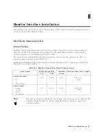
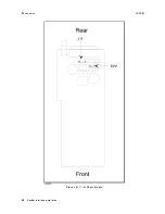
Figure
B-5
shows
the
location
of
the
sockets
in
which
the
pull-up
resistors
(J11)
and
the
switch
with
which
to
select
the
voltage
value
of
EXT
DCV2.
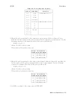
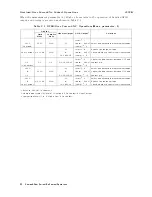
T
able
B-3
lists
the
socket
numbers
for
each
control
signal
and
comparison
signal.
Handler
Interface
Installation
B-7
Содержание 4339B
Страница 10: ......
Страница 18: ... ᄌᦝ 0123 45 6789 8 A B C ᄌᦝ 3 DE FG H FG IJ B C K 9 C Copyright 2007 Agilent Technologies ...
Страница 20: ......
Страница 21: ......
Страница 22: ......
Страница 24: ......
Страница 25: ......
Страница 26: ......
Страница 30: ......
Страница 44: ......
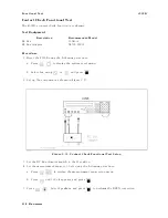
Страница 55: ...4339B Initial Inspection Figure 1 1 Power Cable Supplied Getting Started 1 11 ...
Страница 212: ......
Страница 220: ......
Страница 230: ......
Страница 256: ......
Страница 262: ...4339B Figure B 1 Handler Interface Comparison Output Signals Diagram B 2 Handler Interface Installation ...
Страница 263: ...4339B Figure B 2 Handler Interface Control Output Signals Diagram Handler Interface Installation B 3 ...
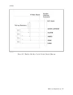
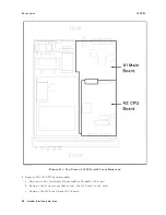
Страница 268: ...Procedure 4339B Figure B 5 A1 Main Board B 8 Handler Interface Installation ...


