


4339B
Getting
Started
T
o
P
erform
OPEN
Correction
The
following
command
performs
an
OPEN
correction:
:SENS:CORR:COLL
OFFS
F
or
example
,
:
DISP
"Connect
the
test
fixture
without
a
DUT,
then
press
`Continue'."
PAUSE
OUTPUT
717;":SENS:FUNC
'CURR'"
Current
measurement
OUTPUT
717;":SENS:CURR:APER
0.39"
Measurement
time
mode:
Long
OUTPUT
717;":SOUR:VOLT
10"
T
est
voltage:
10
V
OUTPUT
717;":OUTP
ON"
Applying
test
voltage
REPEAT
OUTPUT
717;":FETC?"
R
etrieving
the
data
ENTER
717;S,D
UNTIL
ABS(D)<5.E-13
W
ait
until
current
is
within
0.5
pA
OUTPUT
717;":SENS:CORR:COLL
OFFS"
P
erforming
OPEN
correction
OUTPUT
717;"*OPC?"
W
ait
until
OPEN
correction
ends
ENTER
717;A
OUTPUT
717;"OUTP
OFF"
Turning
OFF
test
voltage
:
T
o
Select
the
Measurement
Range
The
following
commands
select
the
measurement
range:
:SENS:CURR:RANG
:SENS:CURR:RANG:AUTO
F
or
example
,
to
select
the
A
uto
range
mode
,
OUTPUT
717;":SENS:CURR:RANG:AUTO
ON"
F
or
example
,
to
select
the
1
nA
range
,
OUTPUT
717;":CURR:RANG:AUTO
OFF"
OUTPUT
717;":CURR:RANG
1E-9"
T
o
Set
the
A
veraging
Rate
The
following
commands
set
the
averaging
rate:
:SENS:AVER
:SENS:AVER:COUN
F
or
example
,
to
set
the
averaging
rate
to
4,
OUTPUT
717;":AVER:COUN
4"
T
o
Set
Trigger
Delay
Time
The
following
command
sets
the
trigger
delay
time:
:TRIG:DEL
F
or
example
,
to
set
the
trigger
delay
time
to
10
ms
,
OUTPUT
717;":TRIG:DEL
1E-2"
Remote
Operation
4-7
Содержание 4339B
Страница 10: ......
Страница 18: ... ᄌᦝ 0123 45 6789 8 A B C ᄌᦝ 3 DE FG H FG IJ B C K 9 C Copyright 2007 Agilent Technologies ...
Страница 20: ......
Страница 21: ......
Страница 22: ......
Страница 24: ......
Страница 25: ......
Страница 26: ......
Страница 30: ......
Страница 44: ......
Страница 55: ...4339B Initial Inspection Figure 1 1 Power Cable Supplied Getting Started 1 11 ...
Страница 212: ......
Страница 220: ......
Страница 230: ......
Страница 256: ......
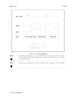
Страница 262: ...4339B Figure B 1 Handler Interface Comparison Output Signals Diagram B 2 Handler Interface Installation ...
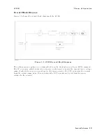
Страница 263: ...4339B Figure B 2 Handler Interface Control Output Signals Diagram Handler Interface Installation B 3 ...
Страница 268: ...Procedure 4339B Figure B 5 A1 Main Board B 8 Handler Interface Installation ...


