


Preparation
for
Use
4339B
Preparation
for
Use
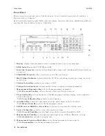
Before
you
use
the
4339B,
you
must
set
it
to
match
the
available
power
line
voltage
and
frequency
.
Set
power
line
voltage|refer
to
\P
ower
Requirements".
Set
power
line
frequency|refer
to
\
Turning
ON
the
4339B "
P
ower
Requirements
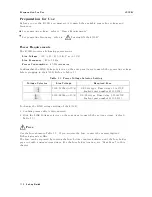
The
4339B
requires
a
following
power
source:
Line
V
oltage
:
100
/
120
/
220
/
240
V
ac
(610%)
Line
Frequency
:
47
to
66
Hz
P
ower
Consumption
:
45
V
A
maximum
Conrm
that
the
LINE
V
oltage
Selector
on
the
rear
panel
is
set
to
match
the
power
line
voltage
before
plugging
in
the
4339B.
Refer
to
T
able
1-1 .
T
able
1-1.
P
ower
V
oltage
Selector
Setting
V
oltage
Selector
Line
V
oltage
Required
Fuse
100V/120V
ac(610%)
UL/CSA
type
,
Time
delay
0.5A
250V
(Agilent
part
number
2110-0202)
220V/240V
ac(610%)
UL/CSA
type
,
Time
delay
0.25A
250V
(Agilent
part
number
2110-0201)
T
o
change
the
LINE
voltage
setting
of
the
4339B:
1.
Conrm
power
cable
is
disconnected.
2.
Slide
the
LINE
V
oltage
selector
on
the
rear
panel
to
match
the
ac
line
voltage
.
(refer
to
T
able
1-1 .)
Fuse
Use
the
fuse
shown
in
T
able
1-1 .
If
you
require
the
fuse
,
contact
the
nearest
Agilent
T
echnologies
sales
oce
.
The
fuse
can
be
replaced
by
turning
the
fuse
holder
counterclockwise
until
the
fuse
holder
pops
out
with
a
minus
screw
driver
.
F
or
the
fuse
holder
location,
see
\Rear
P
anel"
in
this
chapter
.
1-12
Getting
Started
Содержание 4339B
Страница 10: ......
Страница 18: ... ᄌᦝ 0123 45 6789 8 A B C ᄌᦝ 3 DE FG H FG IJ B C K 9 C Copyright 2007 Agilent Technologies ...
Страница 20: ......
Страница 21: ......
Страница 22: ......
Страница 24: ......
Страница 25: ......
Страница 26: ......
Страница 30: ......
Страница 44: ......
Страница 55: ...4339B Initial Inspection Figure 1 1 Power Cable Supplied Getting Started 1 11 ...
Страница 212: ......
Страница 220: ......
Страница 230: ......
Страница 256: ......
Страница 262: ...4339B Figure B 1 Handler Interface Comparison Output Signals Diagram B 2 Handler Interface Installation ...
Страница 263: ...4339B Figure B 2 Handler Interface Control Output Signals Diagram Handler Interface Installation B 3 ...
Страница 268: ...Procedure 4339B Figure B 5 A1 Main Board B 8 Handler Interface Installation ...


