


4339B
High
Capacitance
DUT
Measurement
High
Capacitance
DUT
Measurement
When
the
4339B
measures
a
DUT
that
has
high
capacitance
,
A
C
noise
creates
major
instability
factors
in
the
measurement
because
capacitance
is
sensitive
to
A
C
noise
.
If
you
want
to
measure
the
resistance
of
a
high-capacitance
DUT
maintaining
more
than
10
%
of
S/N
(Signal/Noise)
ratio
,
the
maximum
capacitance
of
the
DUT's
for
each
measurement
range
are
listed
in
T
able
7-1 .
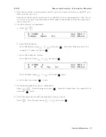
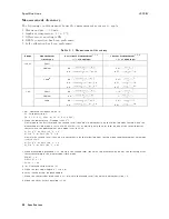
T
able
7-1.
Maximum
Measurable
Capacitance
Measurement
Range
Measurement
Time
Short
Medium
Long
100
pA
|
1
nF
10
nF
1
nA
1
nF
10
nF
100
nF
10
nA
10
nF
100
nF
1
F
100
nA
100
nF
1
F
10
F
1
A
1
F
10
F
100
F
10
A
10
F
100
F
1
mF
100
A
100
F
|
|
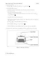
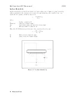
T
o
measure
a
DUT
with
even
higher
capacitance
,
connect
a
resistor
in
series
with
DUT
to
reduce
the
measurement
icker
.
The
16339A
Component
T
est
Fixture
with
its
exchangeable
output
resistors
is
an
ideal
solution
for
this
application.
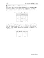
The
16339A
has
four
output
resistor
(100
k,
1
M,
10
M,
and
100
M).
Ideally
,
a
higher
series
resistance
enables
more
stable
measurement.
However
,
there
are
limitations
to
these
resistances
of
each
measurement
range
,
as
listed
in
T
able
7-2 .
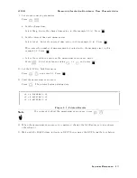
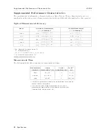
T
able
7-2.
Limit
Output
Resistance
for
Each
Range
Measurement
Range
Output
Resistor
100
pA
100
M
1
nA
10
M
10
nA
1
M
100
nA
100
k
Measurement
Basics
7-5
Содержание 4339B
Страница 10: ......
Страница 18: ... ᄌᦝ 0123 45 6789 8 A B C ᄌᦝ 3 DE FG H FG IJ B C K 9 C Copyright 2007 Agilent Technologies ...
Страница 20: ......
Страница 21: ......
Страница 22: ......
Страница 24: ......
Страница 25: ......
Страница 26: ......
Страница 30: ......
Страница 44: ......
Страница 55: ...4339B Initial Inspection Figure 1 1 Power Cable Supplied Getting Started 1 11 ...
Страница 212: ......
Страница 220: ......
Страница 230: ......
Страница 256: ......
Страница 262: ...4339B Figure B 1 Handler Interface Comparison Output Signals Diagram B 2 Handler Interface Installation ...
Страница 263: ...4339B Figure B 2 Handler Interface Control Output Signals Diagram Handler Interface Installation B 3 ...
Страница 268: ...Procedure 4339B Figure B 5 A1 Main Board B 8 Handler Interface Installation ...


