


4339B
T
o
Retrieve
Data
Eciently
T
o
P
erform
a
Measurement
Sequence
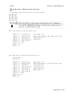
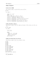
The
following
commands
perform
the
sequence
measurement:
:ARM:SOUR
:ARM:DEL
:TRIG:SOUR
:TRIG:TIM
:TRIG:COUN
W
arning
When
the
4339B
is
in
the
sequence
measurement
mode
,
triggering
a
measurement
may
output
a
dangerous
voltage
levels
up
to
1000
Vdc.
Do
not
touch
the
UNKNO
WN
terminals
or
the
electrodes
of
the
accessory
,
when
the
V
output
indicator
is
ON.
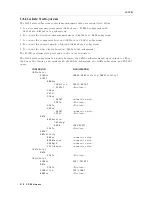
T
o
perform
the
single
measurement
sequence:
:
OUTPUT
717;":SOUR:VOLT
10"
T
est
V
oltage:
10
V
OUTPUT
717;":ARM:SOUR
BUS"
Measurement
Sequence:
ON,
Trigger
Source:
Bus
OUTPUT
717;":ARM:DEL
60"
Charge
time:
60
s
OUTPUT
717;":TRIG:SOUR
INT"
Single
mode
OUTPUT
717;":INIT:CONT
ON"
OUTPUT
717;"*TRG"
ENTER
717;S,D
S,D
:
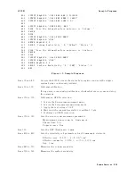
T
o
perform
the
continuous
measurement
sequence:
OPTION
BASE
1
DIM
D(20)
:
OUTPUT
717;":SOUR:VOLT
10"
T
est
V
oltage:
10
V
OUTPUT
717;":ARM:SOUR
BUS"
Measurement
sequence:
ON,
Trigger
Source:
Bus
OUTPUT
717;":ARM:DEL
60"
Charge
time:
60
s
OUTPUT
717;":TRIG:SOUR
TIM"
Continuous
mode
OUTPUT
717;":TRIG:TIM
30"
Interval
time:
30
s
OUTPUT
717;":TRIG:COUN
10"
Memory
size:
10
OUTPUT
717;":INIT:CONT
ON"
OUTPUT
717;"*TRG"
ENTER
717;D(*)
D(*)
:
Remote
Operation
4-25
Содержание 4339B
Страница 10: ......
Страница 18: ... ᄌᦝ 0123 45 6789 8 A B C ᄌᦝ 3 DE FG H FG IJ B C K 9 C Copyright 2007 Agilent Technologies ...
Страница 20: ......
Страница 21: ......
Страница 22: ......
Страница 24: ......
Страница 25: ......
Страница 26: ......
Страница 30: ......
Страница 44: ......
Страница 55: ...4339B Initial Inspection Figure 1 1 Power Cable Supplied Getting Started 1 11 ...
Страница 212: ......
Страница 220: ......
Страница 230: ......
Страница 256: ......
Страница 262: ...4339B Figure B 1 Handler Interface Comparison Output Signals Diagram B 2 Handler Interface Installation ...
Страница 263: ...4339B Figure B 2 Handler Interface Control Output Signals Diagram Handler Interface Installation B 3 ...
Страница 268: ...Procedure 4339B Figure B 5 A1 Main Board B 8 Handler Interface Installation ...


