


Getting
Started
4339B
T
o
Set
the
P
arameters
for
Resistivity
Measurements
The
following
commands
set
the
parameters
for
resistivity
measurements:
:CALC:RES:STH
:CALC:RES:EPER
:CALC:RES:GLEN
:CALC:RES:EAR
F
or
example
,
to
measure
the
volume
resistivity
,
when
the
thickness
of
DUT
is
2
mm,
and
when
you
use
the
50
mm
electrode
and
70
mm
guard
ring
of
the
16008B
Resistivity
Cell,
that
is
,
Thickness
is
0.002
m
Eective
Area
is
0.0019635
(=
2
(0.05/2)
2
)
m
2
Eective
P
erimeter
is
0.1885
(=
2
(0.05+0.07)/2)
m
Gap
is
0.01
(
=(0.0700.05)/2
)
m.
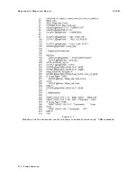
OUTPUT
717;":SENS:FUNC
'RES'"
OUTPUT
717;":CALC:FORM
VRES"
!
OUTPUT
717;":CALC:RES:STH
0.002"
OUTPUT
717;":CALC:RES:EAR
0.0019635"
OUTPUT
717;":CALC:RES:EPER
0.1885"
OUTPUT
717;":CALC:RES:GLEN
0.01"
T
o
Set
Beeper
Mode
The
following
commands
set
the
beeper
mode:
:SYST:BEEP
:SYST:BEEP:STAT
:CALC1:LIM:BEEP
:CALC1:LIM:BEEP:COND
F
or
example
,
to
set
the
beeper
mode
to
emit
a
beep
when
comparison
result
is
P
ASS.
OUTPUT
717;":CALC1:LIM:BEEP:COND
PASS"
T
o
Lock
Out
the
Front
P
anel
K
eys
The
following
command
locks
out
the
front
panel
keys:
:SYST:KLOC
F
or
example
,
to
lock
out
the
front
panel
keys
,
OUTPUT
717;":SYST:KLOC
ON"
T
o
Check
Contact
Integrity
at
the
T
est
Fixture
The
following
command
checks
contacts
at
the
test
xture:
:SENS:CONT:VER
F
or
example
,
to
enable
the
contact
check
function,
OUTPUT
717;":SENS:CONT:VER
ON"
4-8
Remote
Operation
Содержание 4339B
Страница 10: ......
Страница 18: ... ᄌᦝ 0123 45 6789 8 A B C ᄌᦝ 3 DE FG H FG IJ B C K 9 C Copyright 2007 Agilent Technologies ...
Страница 20: ......
Страница 21: ......
Страница 22: ......
Страница 24: ......
Страница 25: ......
Страница 26: ......
Страница 30: ......
Страница 44: ......
Страница 55: ...4339B Initial Inspection Figure 1 1 Power Cable Supplied Getting Started 1 11 ...
Страница 212: ......
Страница 220: ......
Страница 230: ......
Страница 256: ......
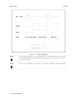
Страница 262: ...4339B Figure B 1 Handler Interface Comparison Output Signals Diagram B 2 Handler Interface Installation ...
Страница 263: ...4339B Figure B 2 Handler Interface Control Output Signals Diagram Handler Interface Installation B 3 ...
Страница 268: ...Procedure 4339B Figure B 5 A1 Main Board B 8 Handler Interface Installation ...


