


Supplemental
P
erformance
Characteristics
4339B
Supplemental
P
erformance
Characteristics
The
supplemental
performance
characteristics
are
listed
below
.
These
characteristics
are
not
specications
but
are
typical
characteristics
included
as
additional
information
for
the
operator
.
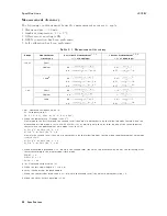
Typical
Measurement
A
ccuracy
Range
Resistance
Measurement
(6
%
of
Readings)
1
Current
Measurement
(6
%
of
Readings)
2
100
pA
0: 86
+
(
100V
o+6
210
012
Rm
Vs
)
0: 7
+
(
6210
012
Im
)
1
nA
0: 74
+
(
100V
o+3
210
011
Rm
Vs
)
0: 58
+
(
3210
011
Im
)
10
nA
0: 56
+
(
100V
o+2
: 5210
0 10
Rm
Vs
)
0: 4
+
(
2:5210
0 10
Im
)
100
nA
0: 53
+
(
100V
o+2
: 5210
0 9
Rm
Vs
)
0: 37
+
(
2:5210
0 9
Im
)
1
A
0: 53
+
(
100V
o+2
: 5210
0 8
Rm
Vs
)
0: 37
+
(
2:5210
0 8
Im
)
1
Rm:
Measured
resistance
value
[]
Vs:
V
oltage
setting
[V]
V
o:
0.1
[V](Vs200
V)
or
0.5
[V](Vs>200
V)
2
Im:
Measured
current
value
[A]
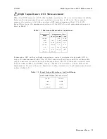
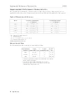
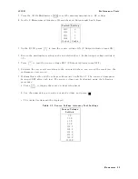
Measurement
Time
The
following
table
lists
some
typical
measurement
times
.
Measurement
Time
Mode
Analog
Measurement
1
[ms]
Digital
Computation
[ms]
T
otal
1
,
2
[ms]
Short
8.5
(10.5)
1.5
10
(12)
Medium
28.5
(30.5)
1.5
30
(32)
Long
385
(387)
5
390
(392)
1
Numbers
in
parenthesis
indicate
the
measurement
times
when
a
contact
check
is
performed.
2
Time
interval
from
a
trigger
command
to
EOM
(end
of
measurement)
signal
output
at
the
handler
interface
port.
(ranging:
hold,
display
mode:
o)
8-8
Specications
Содержание 4339B
Страница 10: ......
Страница 18: ... ᄌᦝ 0123 45 6789 8 A B C ᄌᦝ 3 DE FG H FG IJ B C K 9 C Copyright 2007 Agilent Technologies ...
Страница 20: ......
Страница 21: ......
Страница 22: ......
Страница 24: ......
Страница 25: ......
Страница 26: ......
Страница 30: ......
Страница 44: ......
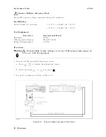
Страница 55: ...4339B Initial Inspection Figure 1 1 Power Cable Supplied Getting Started 1 11 ...
Страница 212: ......
Страница 220: ......
Страница 230: ......
Страница 256: ......
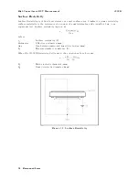
Страница 262: ...4339B Figure B 1 Handler Interface Comparison Output Signals Diagram B 2 Handler Interface Installation ...
Страница 263: ...4339B Figure B 2 Handler Interface Control Output Signals Diagram Handler Interface Installation B 3 ...
Страница 268: ...Procedure 4339B Figure B 5 A1 Main Board B 8 Handler Interface Installation ...


