


Making
a
Measurement
4339B
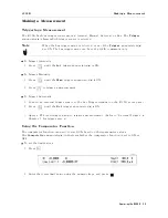
Setting
Contact
Check
The
Cont
Chk
annunciator(
9
)
indicates
the
current
contact
check
status
.
Note
Before
performing
the
contact
check,
perform
an
OPEN
correction
to
measure
the
reference
values
for
the
contact
check.
Refer
to
\
P
erforming
OPEN
Correction
"
in
Chapter
1.
T
o
enable
or
disable
the
contact
check
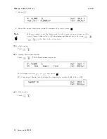
function:
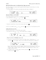
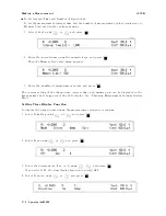
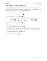
1.
Press
.
2.
Select
ON/OFF
using
or
and
press
to
select.
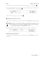
3.
Select
On
or
Off
using
or
,
and
press
to
exit
to
the
previous
display
.
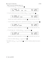
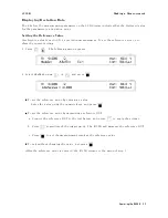
4.
Select
Exit
using
or
,
and
press
to
exit.
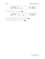
5.
The
Cont
Chk
annunciator(
9
)
turns
ON
if
the
contact
check
function
is
enabled.
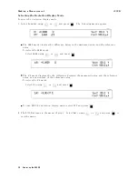
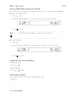
In
the
case
of
the
contact
check
function
is
enabled,
N.C.
(No-Contact)
will
be
displayed
when
the
contacts
between
dut
and
xture
are
open.
The
capacitance
of
the
dut
should
be
shown
below
to
operate
the
contact
check
function
properly
.
C
dut
>
C
s
3
0: 05
+
a
Where:
Cdut
Capacitance
of
dut
Cs
Stracy
capacitance
at
open
measurement
(V
alue
returned
from
the
GPIB
command:SENS:CORR:DATA?
SCAP )
a
V
alue
shown
in
T
able
2-1
T
able
2-1.
V
alue
a
Measurement
Range
Measurement
Time
Mode
Short
Medium
Long
100
pA
|
0.5
pF
0.5
pF
1
nA
0.5
pF
0.5
pF
0.5
pF
10
nA
0.5
pF
0.5
pF
0.7
pF
100
nA
0.7
pF
0.7
pF
1
pF
1
A
1
pF
1
pF
1
pF
10
A
1
pF
1
pF
1
pF
100
A
1
pF
|
|
2-12
Operating
the
4339B
Содержание 4339B
Страница 10: ......
Страница 18: ... ᄌᦝ 0123 45 6789 8 A B C ᄌᦝ 3 DE FG H FG IJ B C K 9 C Copyright 2007 Agilent Technologies ...
Страница 20: ......
Страница 21: ......
Страница 22: ......
Страница 24: ......
Страница 25: ......
Страница 26: ......
Страница 30: ......
Страница 44: ......
Страница 55: ...4339B Initial Inspection Figure 1 1 Power Cable Supplied Getting Started 1 11 ...
Страница 212: ......
Страница 220: ......
Страница 230: ......
Страница 256: ......
Страница 262: ...4339B Figure B 1 Handler Interface Comparison Output Signals Diagram B 2 Handler Interface Installation ...
Страница 263: ...4339B Figure B 2 Handler Interface Control Output Signals Diagram Handler Interface Installation B 3 ...
Страница 268: ...Procedure 4339B Figure B 5 A1 Main Board B 8 Handler Interface Installation ...


