


P
erformance
T
ests
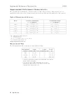
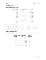
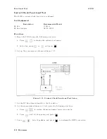
4339B
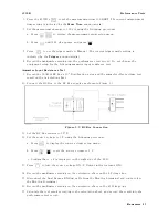
Figure
9-5.
RC
Box
Connection
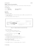
13.
Press
.
Select
I
and
press
to
set
the
measurement
parameter
to
current
(I).
14.
Press
to
set
the
measurement
time
to
LONG.
The
current
measurement
time
setting
is
indicated
by
the
Meas
Time
annunciator(
9
).
15.
Press
to
set
the
trigger
mode
to
Manual.
The
current
trigger
mode
setting
is
indicated
by
the
Trigger
annunciator(
9
).
16.
Set
the
RC
Box
resistor
to
10
10
.
17.
Set
the
source
voltage
to
1
V
using
the
following
procedure:
a.
Press
to
display
the
source
voltage
setup
menu.
b.
Press
to
set
the
source
voltage
to
1
V
.
c.
Conrm
that
+
1
V
is
displayed
on
the
right
side
of
the
LCD
.
18.
Press
to
turn
the
source
voltage
ON.
(V
Output
indicator
turns
ON.)
19.
Press
to
measure
.
20.
Record
the
multimeter
reading
on
the
calculation
sheet
on
the
Multimeter
Reading
line
.
21.
Record
the
4339B
reading
on
the
calculation
sheet
on
the
4339B
Reading
line
.
22.
Press
to
turn
the
source
voltage
OFF
.
(V
Output
indicator
turns
OFF
.)
23.
Calculate
the
test
result
according
to
the
calculation
sheet,
and
record
the
result
into
the
performance
test
record.
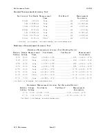
24.
P
erform
this
test
for
all
settings
listed
in
T
able
9-3 .
The
source
voltage
must
be
turned
OFF
after
each
test.
9-10
Maintenance
Содержание 4339B
Страница 10: ......
Страница 18: ... ᄌᦝ 0123 45 6789 8 A B C ᄌᦝ 3 DE FG H FG IJ B C K 9 C Copyright 2007 Agilent Technologies ...
Страница 20: ......
Страница 21: ......
Страница 22: ......
Страница 24: ......
Страница 25: ......
Страница 26: ......
Страница 30: ......
Страница 44: ......
Страница 55: ...4339B Initial Inspection Figure 1 1 Power Cable Supplied Getting Started 1 11 ...
Страница 212: ......
Страница 220: ......
Страница 230: ......
Страница 256: ......
Страница 262: ...4339B Figure B 1 Handler Interface Comparison Output Signals Diagram B 2 Handler Interface Installation ...
Страница 263: ...4339B Figure B 2 Handler Interface Control Output Signals Diagram Handler Interface Installation B 3 ...
Страница 268: ...Procedure 4339B Figure B 5 A1 Main Board B 8 Handler Interface Installation ...


