


4339B
W
aiting
F
or
Completion
Of
Measurement
(detecting
completion
of
measurement)
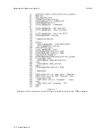
Sample
program
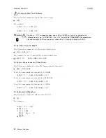
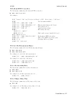
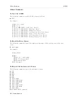
Figure
4-3
shows
a
sample
program
to
detect
the
completion
of
measurement
using
an
SRQ.
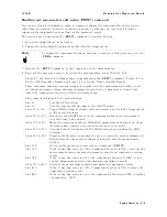
This
program
stops
the
trigger
system,
sets
up
SRQ,
and
then
starts
up
the
trigger
system
once
.
When
an
SRQ
of
the
completion
of
the
measurement
occurs
,
it
displays
a
\Measurement
Complete"
message
and
nishes
.
The
program
is
detailed
below
.
Line
20
Sets
the
GPIB
address
.
Lines
40
to
60
Stops
the
trigger
system
and
sets
the
trigger
mode
to
the
internal
trigger
.
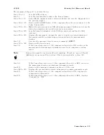
Lines
80
to
90
Enables
bit
4
of
the
operation
status
event
register
and
enables
bit
7
of
the
status
byte
register
.
Lines
100
to
120
Clears
the
status
byte
register
and
operation
status
event
register
.
Lines
140
to
150
Sets
the
branch
destination
of
the
SRQ
interrupt
and
enables
the
SRQ
interrupt.
Lines
160
to
180
Starts
up
the
trigger
system
once
to
start
the
measurement
and
waits
for
the
completion
of
the
measurement.
Line
230
Displays
\Measurement
Complete"
message
.
Figure
4-3.
Detecting
the
completion
of
measurement
using
SRQ
Remote
Operation
4-13
Содержание 4339B
Страница 10: ......
Страница 18: ... ᄌᦝ 0123 45 6789 8 A B C ᄌᦝ 3 DE FG H FG IJ B C K 9 C Copyright 2007 Agilent Technologies ...
Страница 20: ......
Страница 21: ......
Страница 22: ......
Страница 24: ......
Страница 25: ......
Страница 26: ......
Страница 30: ......
Страница 44: ......
Страница 55: ...4339B Initial Inspection Figure 1 1 Power Cable Supplied Getting Started 1 11 ...
Страница 212: ......
Страница 220: ......
Страница 230: ......
Страница 256: ......
Страница 262: ...4339B Figure B 1 Handler Interface Comparison Output Signals Diagram B 2 Handler Interface Installation ...
Страница 263: ...4339B Figure B 2 Handler Interface Control Output Signals Diagram Handler Interface Installation B 3 ...
Страница 268: ...Procedure 4339B Figure B 5 A1 Main Board B 8 Handler Interface Installation ...


