


Status
Reporting
Structure
4339B
Standard
Event
Status
Register
The
Standard
Event
Status
Register
is
frequently
used
and
is
one
of
the
simplest.
Y
ou
can
program
it
using
GPIB
common
commands
,
*ESE
and
*ESR? .
Refer
to
*ESE
command
and
*ESR?
command
in
\Command
Reference
".
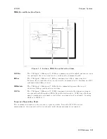
Figure
5-4.
Standard
Event
Status
Register
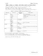
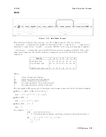
T
able
5-3.
Standard
Event
Status
Register
Assignments
Bit
No
.
Bit
W
eight
Description
7
128
P
ower-On
Bit
|
This
bit
is
set
when
the
4339B
has
been
turned
OFF
and
then
ON
since
the
last
time
this
register
was
read.
6
always
0
(zero)
5
32
Command
Error
Bit
|
This
bit
is
set
if
the
following
command
errors
occur
.
An
IEEE
488.2
syntax
error
occurred.
The
4339B
received
a
Group
Execute
Trigger
(get
)
inside
a
program
message
.
4
16
Execution
Error
Bit
|
This
bit
is
set
when
a
parameter
of
a
GPIB
command
was
outside
of
its
legal
input
range
or
was
otherwise
inconsistent
with
the
4339B's
capabilities
.
3
8
Device-Dependent
Error
Bit
|
This
bit
is
set
when
so
many
errors
have
occurred
that
the
error
queue
is
full.
2
4
Query
Error
Bit
|
This
bit
is
set
when
reading
data
from
the
output
buer
and
no
data
was
present,
or
when
the
data
was
lost.
1
always
0
(zero)
0
1
Operation
Complete
Bit
|
This
bit
is
set
when
the
4339B
has
completed
all
selected
pending
operations
before
sending
the
*OPC
command.
5-42
GPIB
Reference
Содержание 4339B
Страница 10: ......
Страница 18: ... ᄌᦝ 0123 45 6789 8 A B C ᄌᦝ 3 DE FG H FG IJ B C K 9 C Copyright 2007 Agilent Technologies ...
Страница 20: ......
Страница 21: ......
Страница 22: ......
Страница 24: ......
Страница 25: ......
Страница 26: ......
Страница 30: ......
Страница 44: ......
Страница 55: ...4339B Initial Inspection Figure 1 1 Power Cable Supplied Getting Started 1 11 ...
Страница 212: ......
Страница 220: ......
Страница 230: ......
Страница 256: ......
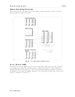
Страница 262: ...4339B Figure B 1 Handler Interface Comparison Output Signals Diagram B 2 Handler Interface Installation ...
Страница 263: ...4339B Figure B 2 Handler Interface Control Output Signals Diagram Handler Interface Installation B 3 ...
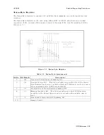
Страница 268: ...Procedure 4339B Figure B 5 A1 Main Board B 8 Handler Interface Installation ...


