

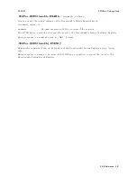


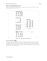


4339B
Status
Reporting
Structure
Standard
Operation
Status
Group
The
4339B
provides
two
Standard
Operation
Status
groups
|
Operation
Status
Register
group
and
Questionable
Status
Register
group
|
which
can
be
accessed
using
the
STATus
subsystem
commands
.
(Refer
to
STATus
subsystem
in
\Command
Reference
".)
This
group
is
used
in
advanced
programming.
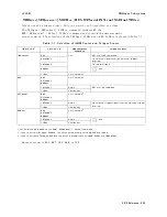
The
individual
bit
assignment
of
these
registers
are
given
in
\Operation
Status
Register"
and
\Questionable
Status
Register"
later
in
this
section.
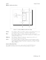
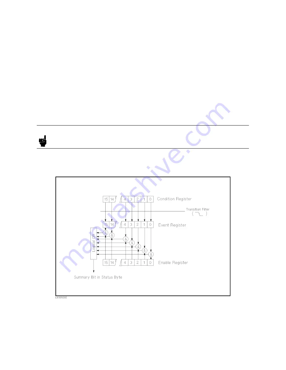
Each
group
includes
a
condition
register
,
an
event
register
,
and
an
enable
resister
.
(Illustrated
in
Figure
5-5.)
The
condition
register
reects
the
internal
states
of
the
4339B.
So
each
time
the
4339B's
condition
is
changed,
its
condition
bit
is
changed
from
\0"
to
\1",
or
from
\1"
to
\0".
The
event
register's
bits
correspond
to
the
condition
register's
bits
.
A
transition
lter
reports
an
event
to
the
event
register
,
when
a
condition
register
bit
changes
from
\1"
to
\0"
for
all
bits
,
except
for
bit
no
.
8
and
9.
F
or
bit
no
.'s
8
and
9,
reporting
occurs
when
a
condition
register
bit
changes
from
\0"
to
\1".
Note
After
the
event
register's
bits
are
set
to
1 ,
the
bits
are
kept
at
1
before
reading
or
clearing
them.
The
enable
register
enables
the
corresponding
bit
in
the
event
register
to
set
the
status
summary
bit,
bit
7
or
bit
3,
of
the
Status
Byte
Register
.
Figure
5-5.
Standard
Operation
Status
Group
Structure
GPIB
Reference
5-43
Содержание 4339B
Страница 10: ......
Страница 18: ... ᄌᦝ 0123 45 6789 8 A B C ᄌᦝ 3 DE FG H FG IJ B C K 9 C Copyright 2007 Agilent Technologies ...
Страница 20: ......
Страница 21: ......
Страница 22: ......
Страница 24: ......
Страница 25: ......
Страница 26: ......
Страница 30: ......
Страница 44: ......
Страница 55: ...4339B Initial Inspection Figure 1 1 Power Cable Supplied Getting Started 1 11 ...
Страница 212: ......
Страница 220: ......
Страница 230: ......
Страница 256: ......
Страница 262: ...4339B Figure B 1 Handler Interface Comparison Output Signals Diagram B 2 Handler Interface Installation ...
Страница 263: ...4339B Figure B 2 Handler Interface Control Output Signals Diagram Handler Interface Installation B 3 ...
Страница 268: ...Procedure 4339B Figure B 5 A1 Main Board B 8 Handler Interface Installation ...


