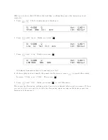
Turning
OFF
T
est
V
oltage
.
.
.
.
.
.
.
.
.
.
.
.
.
.
.
.
.
.
.
.
.
.
.
.
1-24
2.
Operating
the
4339B
Introduction
.
.
.
.
.
.
.
.
.
.
.
.
.
.
.
.
.
.
.
.
.
.
.
.
.
.
.
.
.
.
.
.
.
2-1
Measurement
Conguration
.
.
.
.
.
.
.
.
.
.
.
.
.
.
.
.
.
.
.
.
.
.
.
.
.
2-2
Selecting
the
Measurement
Time
Mode
.
.
.
.
.
.
.
.
.
.
.
.
.
.
.
.
.
.
.
2-2
Setting
the
A
veraging
Rate
.
.
.
.
.
.
.
.
.
.
.
.
.
.
.
.
.
.
.
.
.
.
.
.
.
2-2
Setting
the
Trigger
Delay
Time
.
.
.
.
.
.
.
.
.
.
.
.
.
.
.
.
.
.
.
.
.
.
.
2-2
Setting
the
P
arameters
for
Resistivity
Measurement
.
.
.
.
.
.
.
.
.
.
.
.
.
2-3
Entering
Thickness
of
the
DUT
.
.
.
.
.
.
.
.
.
.
.
.
.
.
.
.
.
.
.
.
.
.
2-3
Setting
the
Electrode
Size
.
.
.
.
.
.
.
.
.
.
.
.
.
.
.
.
.
.
.
.
.
.
.
.
2-3
Making
a
Measurement
.
.
.
.
.
.
.
.
.
.
.
.
.
.
.
.
.
.
.
.
.
.
.
.
.
.
.
.
2-5
Triggering
a
Measurement
.
.
.
.
.
.
.
.
.
.
.
.
.
.
.
.
.
.
.
.
.
.
.
.
.
2-5
Using
the
Comparator
Function
.
.
.
.
.
.
.
.
.
.
.
.
.
.
.
.
.
.
.
.
.
.
.
2-5
Displaying
Deviation
Data
.
.
.
.
.
.
.
.
.
.
.
.
.
.
.
.
.
.
.
.
.
.
.
.
.
2-7
Setting
the
Reference
V
alue
.
.
.
.
.
.
.
.
.
.
.
.
.
.
.
.
.
.
.
.
.
.
.
2-7
Selecting
the
Deviation
Display
Mode
.
.
.
.
.
.
.
.
.
.
.
.
.
.
.
.
.
.
.
2-8
Using
the
Measurement
Sequence
Function
.
.
.
.
.
.
.
.
.
.
.
.
.
.
.
.
.
2-9
Selecting
the
Measurement
Sequence
Mode
.
.
.
.
.
.
.
.
.
.
.
.
.
.
.
.
2-9
Setting
the
Measurement
Sequence
Mode
P
arameters
.
.
.
.
.
.
.
.
.
.
.
2-9
Setting
Time
Display
Function
.
.
.
.
.
.
.
.
.
.
.
.
.
.
.
.
.
.
.
.
.
.
2-10
Starting
Measurement
Sequence
.
.
.
.
.
.
.
.
.
.
.
.
.
.
.
.
.
.
.
2-11
Aborting
Measurement
Sequence
.
.
.
.
.
.
.
.
.
.
.
.
.
.
.
.
.
.
.
.
.
2-11
Setting
Contact
Check
.
.
.
.
.
.
.
.
.
.
.
.
.
.
.
.
.
.
.
.
.
.
.
.
.
.
.
2-12
Reading
the
Limit
Data
of
Contact
Check
Function
.
.
.
.
.
.
.
.
.
.
.
.
2-13
Reading
the
Capacitance
Data
at
DUT
Measurement
.
.
.
.
.
.
.
.
.
.
.
.
2-13
Setting
Current
Limit
.
.
.
.
.
.
.
.
.
.
.
.
.
.
.
.
.
.
.
.
.
.
.
.
.
.
.
2-14
Setting
Current
Monitor
.
.
.
.
.
.
.
.
.
.
.
.
.
.
.
.
.
.
.
.
.
.
.
.
.
.
2-14
Setting
Beeper
Mode
.
.
.
.
.
.
.
.
.
.
.
.
.
.
.
.
.
.
.
.
.
.
.
.
.
.
.
.
2-14
Setting
Display
Mode
and
Display
F
ormat
.
.
.
.
.
.
.
.
.
.
.
.
.
.
.
.
.
.
2-16
Changing
Measurement
Settings
Display
Mode
.
.
.
.
.
.
.
.
.
.
.
.
.
.
.
.
2-17
Saving
and
Recalling
Instrument
Settings
.
.
.
.
.
.
.
.
.
.
.
.
.
.
.
.
.
.
2-18
Locking
Out
the
Front
P
anel
Keys
.
.
.
.
.
.
.
.
.
.
.
.
.
.
.
.
.
.
.
.
.
2-18
Selecting
Local
Mode
.
.
.
.
.
.
.
.
.
.
.
.
.
.
.
.
.
.
.
.
.
.
.
.
.
.
.
.
2-18
Setting
the
GPIB
A
ddress
.
.
.
.
.
.
.
.
.
.
.
.
.
.
.
.
.
.
.
.
.
.
.
.
.
.
2-19
Printing
Measurement
Data
.
.
.
.
.
.
.
.
.
.
.
.
.
.
.
.
.
.
.
.
.
.
.
.
.
2-19
Setting
the
Oset-Error
Canceling
Function
.
.
.
.
.
.
.
.
.
.
.
.
.
.
.
.
.
2-19
T
esting
the
4339B
.
.
.
.
.
.
.
.
.
.
.
.
.
.
.
.
.
.
.
.
.
.
.
.
.
.
.
.
.
.
2-20
P
erforming
a
Self-T
est
.
.
.
.
.
.
.
.
.
.
.
.
.
.
.
.
.
.
.
.
.
.
.
.
.
.
.
2-20
T
esting
the
Front
P
anel
Key's
Functionality
.
.
.
.
.
.
.
.
.
.
.
.
.
.
.
.
.
2-21
If
Y
ou
Have
a
Problem
.
.
.
.
.
.
.
.
.
.
.
.
.
.
.
.
.
.
.
.
.
.
.
.
.
.
.
.
2-22
If
the
Display
is
Blank
and
the
4339B
Appears
Dead
.
.
.
.
.
.
.
.
.
.
.
.
.
2-22
If
an
Error
Message
is
Displayed
.
.
.
.
.
.
.
.
.
.
.
.
.
.
.
.
.
.
.
.
.
.
2-22
If
the
4339B
does
not
A
ccept
Any
Key
Input
.
.
.
.
.
.
.
.
.
.
.
.
.
.
.
.
2-22
If
the
Indicated
V
alue
is
not
Stable
.
.
.
.
.
.
.
.
.
.
.
.
.
.
.
.
.
.
.
.
.
2-22
If
Y
ou
Find
Y
ourself
Lost
When
Operating
the
4339B
.
.
.
.
.
.
.
.
.
.
.
.
.
2-22
Contents-2
Содержание 4339B
Страница 10: ......
Страница 18: ... ᄌᦝ 0123 45 6789 8 A B C ᄌᦝ 3 DE FG H FG IJ B C K 9 C Copyright 2007 Agilent Technologies ...
Страница 20: ......
Страница 21: ......
Страница 22: ......
Страница 24: ......
Страница 25: ......
Страница 26: ......
Страница 30: ......
Страница 44: ......
Страница 55: ...4339B Initial Inspection Figure 1 1 Power Cable Supplied Getting Started 1 11 ...
Страница 212: ......
Страница 220: ......
Страница 230: ......
Страница 256: ......
Страница 262: ...4339B Figure B 1 Handler Interface Comparison Output Signals Diagram B 2 Handler Interface Installation ...
Страница 263: ...4339B Figure B 2 Handler Interface Control Output Signals Diagram Handler Interface Installation B 3 ...
Страница 268: ...Procedure 4339B Figure B 5 A1 Main Board B 8 Handler Interface Installation ...

