


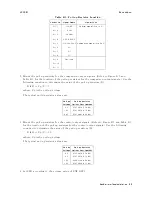


Overload/Over-Current/No-Contact
Operations
4339B
When
the
measurement
parameter
is
I,
High
or
Low
status
in
the
operation
of
handler/GPIB
output
and
display
is
reversed
as
shown
in
T
able
C-2.
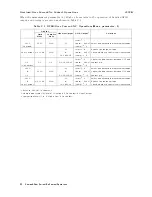
T
able
C-2.
O
VLD/Over-Current/N.C.
Operations(Meas
.
parameter:
I)
Display
Handler
Output
GPIB
Output
1
Solutions
Data
Mode
Comprtr
Mode
<stat>
2
:
1
O
VLD
O
VLD
HIGH
/HI
<data>:
9.9E37
Select
an
appropriate
measurement
range
.
(Overload)
<comp>
3
:
2
/HI
<stat>
2
:
4
Reduce
the
source
voltage
.
Over-Current
O
V
CURR
HIGH
&
<data>:
9.9E37
Check
whether
a
short
circuit
is
occurred.
/NOT
READY
<comp>
3
:
2
<stat>
2
:
2
Cancel
the
bad
contact
between
DUT
and
N.C.
N.C.
N.C.
/NO
CONT
A
CT
<data>:
9.9E37
contact-pin.
(No-Contact)
<comp>
3
:
8
O
VLD
/HI
<stat>
2
:
3
Select
an
appropriate
measurement
range
.
&
O
VLD
HIGH
&
<data>:
9.9E37
Cancel
the
bad
contact
between
DUT
and
N.C.
/NO
CONT
A
CT
<comp>
3
:
10
contact-pin.
O
VLD
/HI
<stat>
2
:
5
Select
an
appropriate
measurement
range
.
&
O
V
CURR
HIGH
&
<data>:
9.9E37
Reduce
the
source
voltage
.
Over-Current
/NOT
READY
<comp>
3
:
2
Check
whether
a
short
circuit
is
occurred.
1
Refer
to
:FETCh?
in
Chapter
5
2
Measurement
status
(0:Normal,
1:Overload,
2:No-Contact,
4:Over-Current)
3
Comparison
result
(1:In,
2:High,
4:Low
,
8:No-Contact)
C-2
Overload/Over-Current/No-Contact
Operations
Содержание 4339B
Страница 10: ......
Страница 18: ... ᄌᦝ 0123 45 6789 8 A B C ᄌᦝ 3 DE FG H FG IJ B C K 9 C Copyright 2007 Agilent Technologies ...
Страница 20: ......
Страница 21: ......
Страница 22: ......
Страница 24: ......
Страница 25: ......
Страница 26: ......
Страница 30: ......
Страница 44: ......
Страница 55: ...4339B Initial Inspection Figure 1 1 Power Cable Supplied Getting Started 1 11 ...
Страница 212: ......
Страница 220: ......
Страница 230: ......
Страница 256: ......
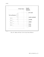
Страница 262: ...4339B Figure B 1 Handler Interface Comparison Output Signals Diagram B 2 Handler Interface Installation ...
Страница 263: ...4339B Figure B 2 Handler Interface Control Output Signals Diagram Handler Interface Installation B 3 ...
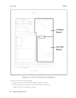
Страница 268: ...Procedure 4339B Figure B 5 A1 Main Board B 8 Handler Interface Installation ...


