

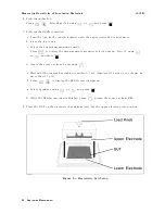


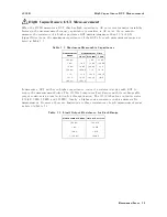


High
Capacitance
DUT
Measurement
4339B
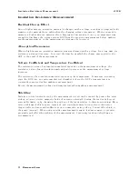
In
addition,
T
able
7-3
shows
the
appropriate
resistor
for
each
range
and
measurement
time
mode
.
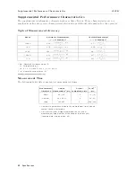
T
able
7-3.
Appropriate
Output
Resistance
for
Range
Measurement
Range
Measurement
Time
Mode
Short
Medium
Long
100
pA
|
10
M
(100
M
1
)
10
M(100
M
1
)
1
nA
10
M
1
M
1
M
10
nA
1
M
100
k
100
k
100
nA
100
k
(100
k)
2
(100
k)
2
1
A
(100
k)
2
Short
Bar
3
Short
Bar
3
10
A
Short
Bar
3
Short
Bar
3
Short
Bar
3
100
A
Short
Bar
3
|
|
1
100
M
resistor
is
eective
for
measuring
current
less
than
10
pA
in
100
pA
range
.
2
Using
100
k
resistor
is
recommended,
but
the
response
will
become
slow
.
3
4339B 's
internal
input
and
output
resistance
are
sucient,
so
an
extra
resistor
in
series
is
not
necessary
,
in
this
range
and
mode
.
Note
Using
a
high
resistance
in
series
with
the
DUT
causes
the
charging
time
constant
to
increase
,
thereby
increasing
the
necessary
measurement
time
.
W
arning
Do
NO
T
touch
the
electrode
and
UNKNO
WN
connector
while
the
High
V
oltage
indicator
is
lit
which
shows
the
4339B 's
output
is
a
high
voltage
levels
up
to
1000
Vdc
maximum.
Y
ou
must
operate
after
turning
o
the
voltage
source
output
and
you
have
conrmed
the
high
voltage
indicator
is
turned
o.
7-6
Measurement
Basics
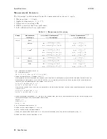
Содержание 4339B
Страница 10: ......
Страница 18: ... ᄌᦝ 0123 45 6789 8 A B C ᄌᦝ 3 DE FG H FG IJ B C K 9 C Copyright 2007 Agilent Technologies ...
Страница 20: ......
Страница 21: ......
Страница 22: ......
Страница 24: ......
Страница 25: ......
Страница 26: ......
Страница 30: ......
Страница 44: ......
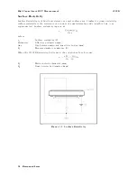
Страница 55: ...4339B Initial Inspection Figure 1 1 Power Cable Supplied Getting Started 1 11 ...
Страница 212: ......
Страница 220: ......
Страница 230: ......
Страница 256: ......
Страница 262: ...4339B Figure B 1 Handler Interface Comparison Output Signals Diagram B 2 Handler Interface Installation ...
Страница 263: ...4339B Figure B 2 Handler Interface Control Output Signals Diagram Handler Interface Installation B 3 ...
Страница 268: ...Procedure 4339B Figure B 5 A1 Main Board B 8 Handler Interface Installation ...


