
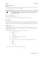


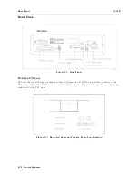


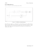


Rear
P
anel
4339B
Handler
Interface
Handler
interface
is
used
to
synchronize
timing
with
an
external
handler
.
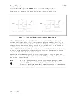
Before
using
the
handler
interface
,
you
must
connect
pull-up
resisters
to
enable
the
output
signals
and
set
the
dip
switch
to
select
the
voltage
level
to
match
the
input
signals
.
Refer
to
Appendix
B
for
these
procedures
.
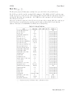
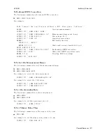
Specications
Output
signal
:
Negative
TRUE,
open
collector
,
opto-isolated
Decision
Output:
Primary
parameter
Comparator
High,
In,
Low
Secondary
parameter
Comparator
High,
In,
Low
DUT
and
test
electrode's
contact
failed.
Index:
Analog
measurement
complete
Measurement
complete:
Full
measurement
complete
Alarm:
Notication
that
a
momentary
power
failure
was
detected
or
the
error
occurs
.
Input
Signal
:
Opto-isolated
K
eylock:
Front
panel
keyboard
lockout
External
Trigger:
Pulse
width
1
s
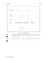
Figure
3-6.
Pin
Assignment
for
Handler
Interface
Connector
3-22
Function
Reference
Содержание 4339B
Страница 10: ......
Страница 18: ... ᄌᦝ 0123 45 6789 8 A B C ᄌᦝ 3 DE FG H FG IJ B C K 9 C Copyright 2007 Agilent Technologies ...
Страница 20: ......
Страница 21: ......
Страница 22: ......
Страница 24: ......
Страница 25: ......
Страница 26: ......
Страница 30: ......
Страница 44: ......
Страница 55: ...4339B Initial Inspection Figure 1 1 Power Cable Supplied Getting Started 1 11 ...
Страница 212: ......
Страница 220: ......
Страница 230: ......
Страница 256: ......
Страница 262: ...4339B Figure B 1 Handler Interface Comparison Output Signals Diagram B 2 Handler Interface Installation ...
Страница 263: ...4339B Figure B 2 Handler Interface Control Output Signals Diagram Handler Interface Installation B 3 ...
Страница 268: ...Procedure 4339B Figure B 5 A1 Main Board B 8 Handler Interface Installation ...


