


4339B
Making
a
Measurement
Making
a
Measurement
Triggering
a
Measurement
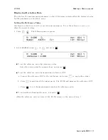
The
4339B
has
four
trigger
source
modes:
Internal,
Manual,
External,
or
Bus
.
The
Trigger
annunciator(
9
)
shows
which
trigger
source
is
selected.
Note
When
the
bus
trigger
mode
is
selected,
none
of
the
Trigger
annunciators(
9
)
are
ON.
The
bus
trigger
mode
can
be
set
by
GPIB
commands
only
.
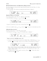
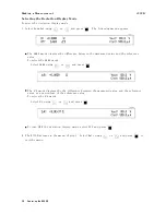
T
o
Trigger
Internally
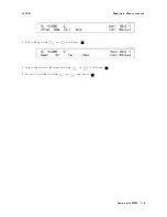
1.
Press
until
the
Int
trigger
annunciator(
9
)
is
ON.
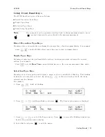
T
o
Trigger
Manually
1.
Press
until
the
Man
trigger
annunciator(
9
)
is
ON.
2.
Press
to
trigger
a
measurement.
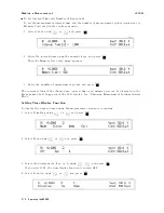
T
o
Trigger
Externally
1.
Connect
an
external
trigger
source
to
the
Ext
Trigger
terminal
on
the
4339B's
rear
panel.
2.
Press
until
the
Ext
trigger
annunciator(
9
)
is
ON.
3.
Apply
a
TTL
level
trigger
signal
to
trigger
a
measurement.
(Refer
to
\External
Trigger"
in
Chapter
3
for
trigger
spec's
.)
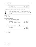
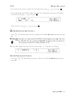
Using
the
Comparator
Function
The
comparator
function
can
used
to
sort
DUT
s
based
on
their
parameter
values
.
The
Comprtr
On
annunciator(
9
)
indicates
whether
the
comparator
function
is
set
to
ON
or
OFF
.
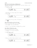
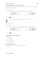
T
o
set
the
limit
values:
1.
Press
.
2.
Enter
the
lower
limit
value
using
the
numeric
keys
,
and
press
.
Operating
the
4339B
2-5
Содержание 4339B
Страница 10: ......
Страница 18: ... ᄌᦝ 0123 45 6789 8 A B C ᄌᦝ 3 DE FG H FG IJ B C K 9 C Copyright 2007 Agilent Technologies ...
Страница 20: ......
Страница 21: ......
Страница 22: ......
Страница 24: ......
Страница 25: ......
Страница 26: ......
Страница 30: ......
Страница 44: ......
Страница 55: ...4339B Initial Inspection Figure 1 1 Power Cable Supplied Getting Started 1 11 ...
Страница 212: ......
Страница 220: ......
Страница 230: ......
Страница 256: ......
Страница 262: ...4339B Figure B 1 Handler Interface Comparison Output Signals Diagram B 2 Handler Interface Installation ...
Страница 263: ...4339B Figure B 2 Handler Interface Control Output Signals Diagram Handler Interface Installation B 3 ...
Страница 268: ...Procedure 4339B Figure B 5 A1 Main Board B 8 Handler Interface Installation ...


