


Theory
of
Operation
4339B
Theory
of
Operation
This
section
provides
the
4339B's
theory
of
operation.
In
\Overall
Measurement
Theory"
and
\Overall
Block
Diagram
",
we
will
discuss
the
measurement
theory
with
the
ungrounded
DUT
measurement
conguration.
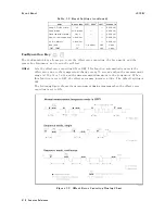
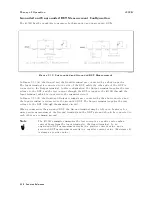
These
descriptions
can
also
be
applied
to
the
measurement
of
a
grounded
DUT
,
considering
the
test
signal
ow
shown
in
Figure
3-10
(b).
Overall
Measurement
Theory
The
4339B
measures
the
Device
Under
T
est
(DUT)
resistance
in
the
following
manner
.
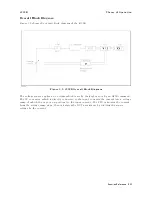
Figure
3-8.
Simplied
Model
of
Impedance
Measurement
Figure
3-8
shows
a
simplied
model
of
the
4339B
measuring
a
DUT
.
In
the
Figure
3-8,
the
DUT
is
connected
in
series
with
a
test
voltage
source
,
V
,
and
an
ammeter
,
A.
Rs
is
the
4339B 's
source
resistance
(R s
=
1k
)
and
Ri
is
the
input
resistance
(R i
=
1k
).
In
the
resistance
measurement
mode
(the
measurement
parameter
is
R),
the
4339B
displays
the
\derived"
DUT
resistance
,
Rx.
In
other
words
,
if
the
ammeter
measures
Ix
when
the
source
voltage
is
V,
the
4339B
displays
the
DUT
resistance
Rx,
calculated
using
the
following
equation:
R x
=
V
I
x
0
(R s
+
R i)
In
the
current
measurement
mode
(the
measurement
parameter
is
I),
the
4339B
measures
the
actual
current
value
,
Ix,
which
ows
through
the
DUT
,
and
displays
the
value
for
the
measurement
result.
F
or
example
,
if
R
x
is
100
k,
and
V
is
1
V,
the
measurement
result
will
be
9.8
A
(
1 V
100 k
+2k
).
If
you
measure
a
DUT
whose
resistance
value
is
lower
,
the
4339B 's
source
resistance
,
Rs,
and
input
resistance
,
Ri,
aect
the
measurement
current
value
,
Ix,
more
.
3-26
Function
Reference
Содержание 4339B
Страница 10: ......
Страница 18: ... ᄌᦝ 0123 45 6789 8 A B C ᄌᦝ 3 DE FG H FG IJ B C K 9 C Copyright 2007 Agilent Technologies ...
Страница 20: ......
Страница 21: ......
Страница 22: ......
Страница 24: ......
Страница 25: ......
Страница 26: ......
Страница 30: ......
Страница 44: ......
Страница 55: ...4339B Initial Inspection Figure 1 1 Power Cable Supplied Getting Started 1 11 ...
Страница 212: ......
Страница 220: ......
Страница 230: ......
Страница 256: ......
Страница 262: ...4339B Figure B 1 Handler Interface Comparison Output Signals Diagram B 2 Handler Interface Installation ...
Страница 263: ...4339B Figure B 2 Handler Interface Control Output Signals Diagram Handler Interface Installation B 3 ...
Страница 268: ...Procedure 4339B Figure B 5 A1 Main Board B 8 Handler Interface Installation ...


