


Getting
Started
4339B
T
o
Control
the
4339B
from
an
External
Computer
Most
measurements
can
be
modeled
by
the
following
simple
four
step
sequence:
1.
Set
up
the
instrument.
Typically
,
you
begin
the
setup
step
by
sending
the
*RST
command
to
set
the
instrument
to
its
default
settings
.
Next,
if
you
need
values
dierent
from
the
default
settings
,
change
the
settings
one
by
one
as
required.
2.
Trigger
the
measurement.
The
trigger
may
be
generated
automatically
by
steps
taken
in
your
setup
commands
,
or
you
may
send
an
explicit
trigger
command.
T
o
select
the
trigger
source
,
send
the
:TRIG:SOUR
command
with
the
trigger
source
parameter
.
When
you
select
BUS
as
the
trigger
source
,
sending
*TRG
triggers
a
measurement
and
retrieves
the
measurement
data.
3.
Retrieving
the
data.
4.
Turn
OFF
the
test
voltage
and
end
the
measurement.
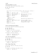
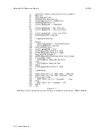
Figure
4-1
shows
a
simple
resistance
measurement
program.
:
!
Step
1
OUTPUT
717;"*RST"
R
esetting
OUTPUT
717;":INIT:CONT
ON"
Initializing
trigger
system
OUTPUT
717;":FUNC
'RES'"
R
esistance
measurement
OUTPUT
717;":SOUR:VOLT
10"
T
est
voltage:
10
V
OUTPUT
717;":OUTP
ON"
Applying
test
voltage
OUTPUT
717;":TRIG:SOUR
BUS"
Trigger
source:
Bus
!
Step
2
OUTPUT
717;"*TRG"
Triggering
!
Step
3
ENTER
717;R_value
R
etrieving
the
data
!
Step
4
OUTPUT
717;":OUTP
OFF"
Turning
OFF
test
voltage
:
Figure
4-1.
Simple
Program
Example
The
following
sections
describes
how
to
perform
specic
tasks
.
4-4
Remote
Operation
Содержание 4339B
Страница 10: ......
Страница 18: ... ᄌᦝ 0123 45 6789 8 A B C ᄌᦝ 3 DE FG H FG IJ B C K 9 C Copyright 2007 Agilent Technologies ...
Страница 20: ......
Страница 21: ......
Страница 22: ......
Страница 24: ......
Страница 25: ......
Страница 26: ......
Страница 30: ......
Страница 44: ......
Страница 55: ...4339B Initial Inspection Figure 1 1 Power Cable Supplied Getting Started 1 11 ...
Страница 212: ......
Страница 220: ......
Страница 230: ......
Страница 256: ......
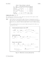
Страница 262: ...4339B Figure B 1 Handler Interface Comparison Output Signals Diagram B 2 Handler Interface Installation ...
Страница 263: ...4339B Figure B 2 Handler Interface Control Output Signals Diagram Handler Interface Installation B 3 ...
Страница 268: ...Procedure 4339B Figure B 5 A1 Main Board B 8 Handler Interface Installation ...


