


4339B
CALCulate
Subsystem
The
CALCulate
subsystem
controls
measurement
data
processing
listed
below
.
1.
T
o
select
measurement
parameter
(CALCulate1:FORMat
subsystem
with
CALCulate:RESistivity
subsystem)
2.
T
o
control
the
deviation
measurement
mode
(CALCulate1:MATH
subsystem)
3.
T
o
control
the
comparator
function
(CALCulate1:LIMit
subsystem)
4.
T
o
control
the
current
monitor
function
(CALCulate2
subsystem)
5.
T
o
control
the
time
display
function
(CALCulate3
subsystem)
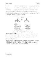
The
4339B
performs
data
processing
in
the
order
it
is
listed.
The
CALCulate
subsystem
is
logically
between
the
SENSe
subsystem
and
data
output
to
either
the
bus
or
the
display
,
and
works
with
the
SENSe
subsystem,
the
D
A
T
A
subsystem,
and
FETCh?
query
.
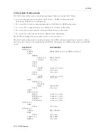
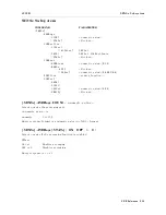
COMMAND
P
ARAMETER
CALCulate1
:FORMat
{REAL|SRESistivity|VRESistivity}
:LIMit
:BEEPer
:CONDition
{FAIL|PASS}
[:STATe]
<Boolean>
:CLEar
:FAIL?
:LOWer
[:DATA]
<numeric
value>
:STATe
<Boolean>
:STATe
<Boolean>
:UPPer
[:DATA]
<numeric
value>
:STATe
<Boolean>
:MATH
:EXPRession
:CATalog?
:NAME
f DEV jPCNT g
:STATe
<Boolean>
:PATH?
:RESistivity
:EARea
<numeric
value>
:EPERimeter
<numeric
value>
:GLENgth
<numeric
value>
:STHickness
<numeric
value>
CALCulate2
:MATH
:STATe
<Boolean>
CALCulate3
:FORMat
{SEC|TPCNT}
:MATH
:STATe
<Boolean>
:DIRECtion
{UP|DOWN}
:BEEPer
<Boolean>
5-10
GPIB
Reference
Содержание 4339B
Страница 10: ......
Страница 18: ... ᄌᦝ 0123 45 6789 8 A B C ᄌᦝ 3 DE FG H FG IJ B C K 9 C Copyright 2007 Agilent Technologies ...
Страница 20: ......
Страница 21: ......
Страница 22: ......
Страница 24: ......
Страница 25: ......
Страница 26: ......
Страница 30: ......
Страница 44: ......
Страница 55: ...4339B Initial Inspection Figure 1 1 Power Cable Supplied Getting Started 1 11 ...
Страница 212: ......
Страница 220: ......
Страница 230: ......
Страница 256: ......
Страница 262: ...4339B Figure B 1 Handler Interface Comparison Output Signals Diagram B 2 Handler Interface Installation ...
Страница 263: ...4339B Figure B 2 Handler Interface Control Output Signals Diagram Handler Interface Installation B 3 ...
Страница 268: ...Procedure 4339B Figure B 5 A1 Main Board B 8 Handler Interface Installation ...


