2.6.4.7.2 Wiring
For the maximum possible cable lengths within an Ethernet network, various factors have to
be taken into account. Twisted pair cables (TP cables) are used as transmission medium for
10 Mbit/s Ethernet (10Base-T) as well as for 100 Mbit/s (Fast) Ethernet (100Base-TX). For a
transmission rate of 10 Mbit/s, cables of at least category 3 (IEA/TIA 568-A-5 Cat3) or class C
(according to European standards) are allowed. For fast Ethernet with a transmission rate of
100 Mbit/s, cables of category 5 (Cat5) or class D or higher have to be used. The maximum
length of a segment, which is the maximum distance between two network components, is
restricted to 100 m due to the electric properties of the cable.
Furthermore, the length restriction for one collision domain has to be observed. A collision
domain is the area within a network which can be affected by a possibly occurring collision
(i.e. the area the collision can propagate over). This, however, only applies if the components
operate in half-duplex mode since the CSMA/CD access method is only used in this mode. If
the components operate in full-duplex mode, no collisions can occur. Reliable operation of the
collision detection method is important, which means that it has to be able to detect possible
collisions even for the smallest possible frame size of 64 bytes (512 bits). But this is only
guaranteed if the first bit of the frame arrives at the most distant subscriber within the collision
domain before the last bit has left the transmitting station. Furthermore, the collision must
be able to propagate to both directions at the same time. Therefore, the maximum distance
between two ends must not be longer than the distance corresponding to the half signal propa-
gation time of 512 bits. Thus, the resulting maximum possible length of the collision domain is
2000 m for a transmission rate of 10 Mbit/s and 200 m for 100 Mbit/s. In addition, the bit delay
times caused by the passed network components also have to be considered.
The following table shows the specified properties of the respective cable types per 100 m.
Table 203: Specified cable properties:
Parameter
10Base-T [10 MHz]
100Base-TX [100 MHz]
Attenuation [dB / 100m]
10.7
23.2
NEXT [dB / 100m]
23
24
ACR [dB / 100m]
N/A
4
Return loss [dB / 100m]
18
10
Wave impedance [Ohms]
100
100
Category
3 or higher
5
Class
C or higher
D or higher
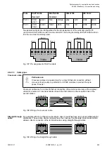
The TP cable has eight wires arranged in four pairs of twisted wires. Different color codes
exist for the coding of the wires, the coding according to EIA/TIA 568, version 1, being the one
most commonly used. In this code, the individual pairs are coded with blue, orange, green and
brown color. One wire of a pair is unicolored and the corresponding second wire is striped,
the respective color alternating with white. For shielded cables, a distinction is made between
cables that have one single shield around all pairs of wires and cables that have an additional
individual shield for each pair of wires. The following table shows the different color coding
systems for TP cables:
Table 204: Color coding of TP cables:
Pairs
EIA/TIA 568
Version 1
EIA/TIA 568
Version 2
DIN 47100
IEC 189.2
Pair 1
white/
blue
blue
green
red
white
brown
white
blue
Pair 2
white/
orange
orange
black
yellow
green
yellow
white
orange
Cable length
restrictions
TP cable
System assembly, construction and connection
AC500 (Standard) > Connection and wiring
2022/01/31
3ADR010278, 3, en_US
998


