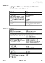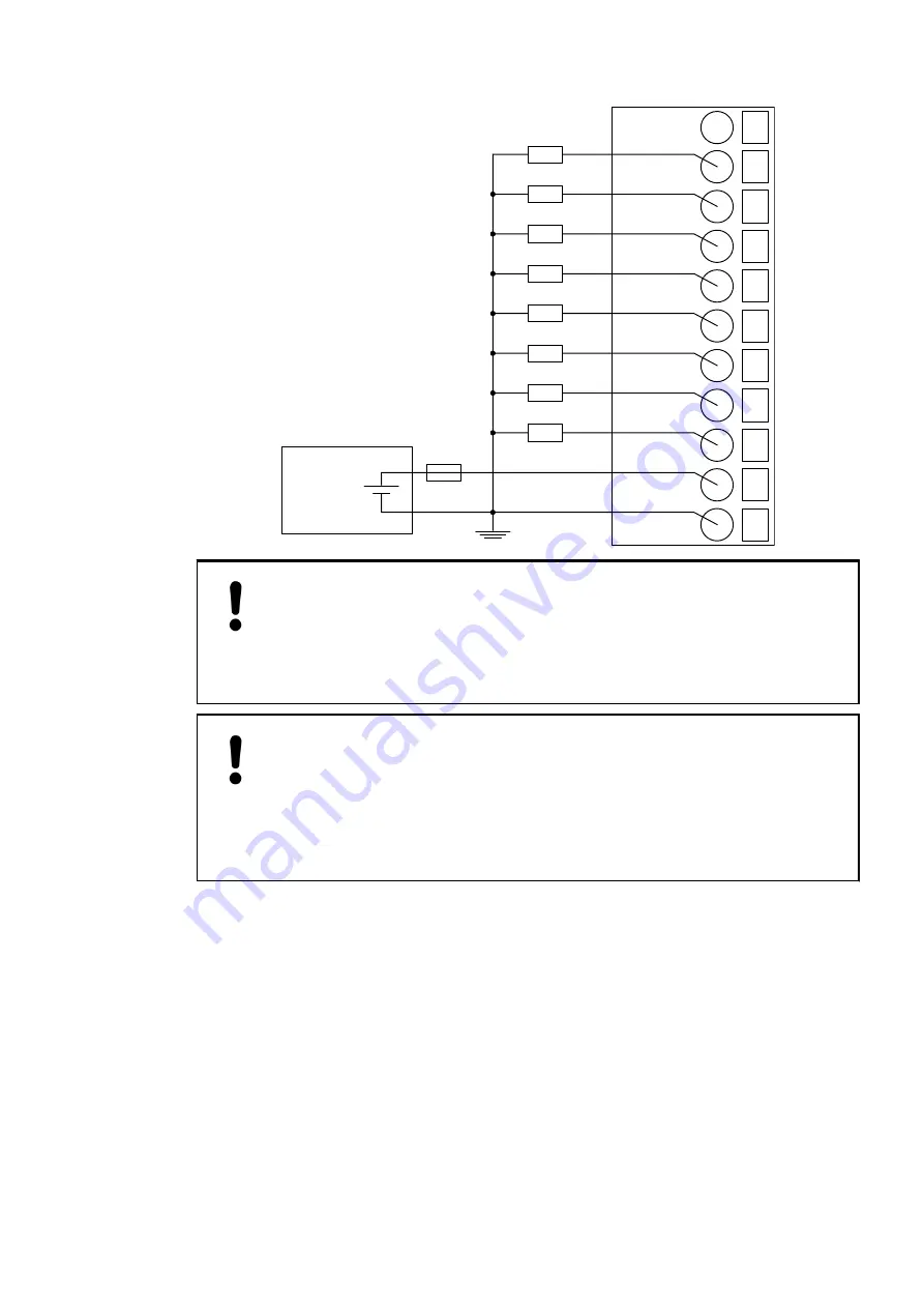
10
11
−−−
O0
13 O2
12 O1
14 O3
15 O4
16 O5
17 O6
18 O7
19 UP
20 ZP
24 VDC
−
+
NOTICE!
Risk of malfunctions in the plant!
The outputs may switch on for a period of 10 to 50
µ
s if the process supply
voltage UP/ZP is switched on.
This must be considered in the planning of the application.
NOTICE!
Risk of damaging the I/O module!
The outputs are not protected against short circuits and overload.
–
Never short-circuit or overload the outputs.
–
Never connect the outputs to other voltages.
–
Use an external 3 A fast-protection fuse for the outputs.
The module provides several diagnosis functions (see Diagnosis
The meaning of the LEDs is described in the section State LEDs
I/O configuration
The module itself does not store configuration data. It receives its parameterization data from
the master device of the I/O bus (CPU or communication interface module) during power-up of
the system.
Hence, replacing I/O modules is possible without any re-parameterization via software.
Device specifications
I/O modules > Digital I/O modules
2022/01/31
3ADR010278, 3, en_US
197

