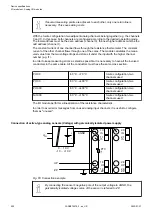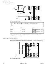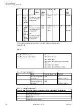
Digital input
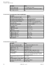
24 V
1 channel used
Effect of incorrect input ter-
minal connection
Wrong or no signal detected,
no damage up to 35 V
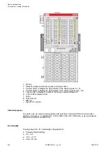
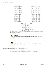
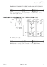
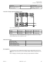
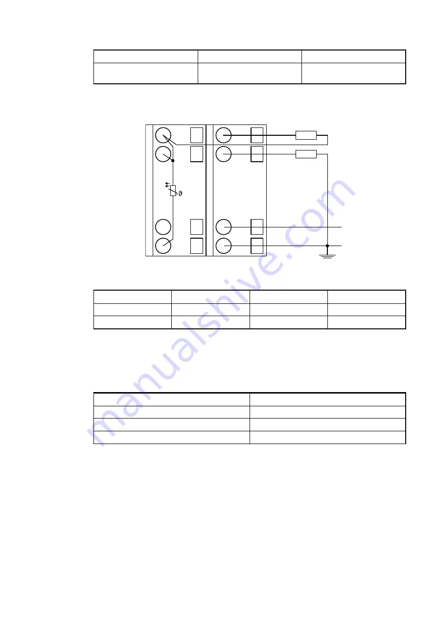
Connection of analog output loads (Voltage, current)
UP
ZP
3.0
O0-
3.1
O1-
3.8
UP
3.9
ZP
PTC
4.0
O0+
4.1
O1+
4.8
UP
4.9
ZP
-10 ... +10 V
0 ... 20 mA
4 ... 20 mA
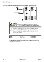
Fig. 71: Connection example
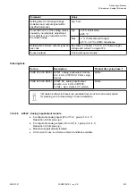
Voltage
-10 V...+10 V
Load max.
±
10 mA
1 channel used
Current
0 mA...20 mA
Load 0
W
...500
W
1 channel used
Current
4 mA...20 mA
Load 0
W
...500
W
1 channel used
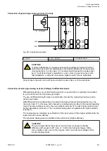
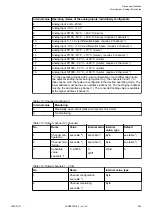
Only the channels 0...3 can be configured as current output (0 mA...20 mA or 4 mA...20 mA).
Unused analog outputs can be left open-circuited.
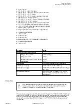
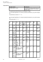
Internal data exchange
Digital inputs (bytes)
0
Digital outputs (bytes)
0
Counter input data (words)
8
Counter output data (words)
8
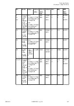
I/O configuration
The module does not store configuration data itself. It gets its parameterization data from the
master device of the I/O bus (CPU or communication interface module) during power-up of the
system.
Hence, replacing I/O modules is possible without any re-parameterization via software.
Device specifications
I/O modules > Analog I/O modules
2022/01/31
3ADR010278, 3, en_US
535


