1.0
I0-
1.1
I0B
1.8
UP
1.9
ZP
PTC
2.0
I0+
2.1
I0A
2.8
UP
2.9
ZP
UP
ZP
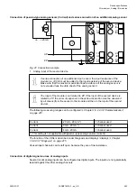
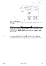
Fig. 42: Connection example
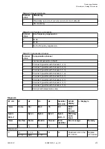
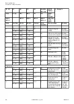
The following operating mode can be configured
Chapter 1.6.2.2.3.6 “Parameterization”
Digital input
24 V
1 channel used
Effect of incorrect input ter-
minal connection
Wrong or no signal detected,
no damage up to 35 V
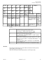
For a description of the function of the LEDs, please refer to Diagnosis and displays / displays
Chapter 1.6.2.2.3.7 “Diagnosis” on page 475
Connection of resistance thermometers in 2-wire configuration
When resistance thermometers (Pt100, Pt1000, Ni1000, Cu50) are used, a constant current
must flow through them to build the necessary voltage drop for the evaluation. For this, the
module AI531 provides a constant current source which is multiplexed over the 4 analog chan-
nels.
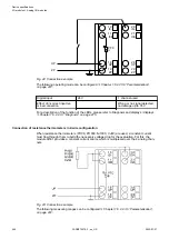
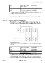
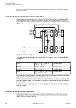
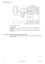
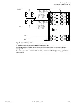
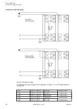
Fig. 43: Connection example
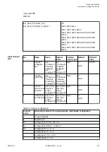
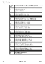
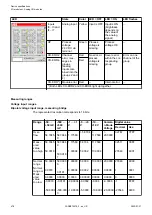
The following measuring ranges can be configured
Chapter 1.6.2.2.3.6 “Parameterization”
Device specifications
I/O modules > Analog I/O modules
2022/01/31
3ADR010278, 3, en_US
464


