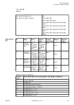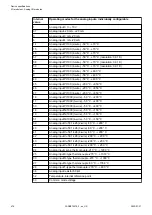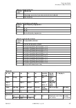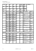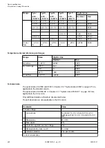
Parameter
Value
From 24 V DC power supply at the termi-
nals UP/L+ and ZP/M of the CPU/communi-
cation interface module
Ca. 2 mA
Current consumption from UP in normal
operation
130 mA
Inrush current from UP (at power up)
0.056 A
2
s
Max. length of analog cables, conductor cross
section > 0.14 mm
²
100 m
Weight
130 g
Mounting position
Horizontal or vertical with derating (max.
temperature 40 °C)
Cooling
The natural convection cooling must not be
hindered by cable ducts or other parts in the
switchgear cabinet.
NOTICE!
Attention:
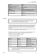
All I/O channels (digital and analog) are protected against reverse polarity,
reverse supply, short circuit and continuous overvoltage up to 30 V DC.
Technical data of the analog inputs
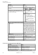
Parameter
Value
Number of channels per module
8
Distribution of channels into groups
2 groups of 4 channels each
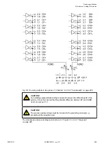
Connections of the channels I0 to I3
Terminals 1.0 to 1.7 and terminals 2.0 to
2.7
Connections of the channels I4 to I7
Terminals 3.0 to 3.7 and terminals 4.0 to
4.7
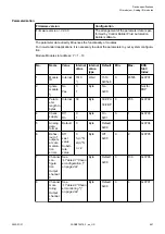
Input type
Bipolar (not with current or Pt100/
Pt1000/ Ni1000/ Cu50/ resistor)
Galvanic isolation
Against internal supply and other
modules
Common mode input range
±
20 V DC plus signal voltage
Configurability
Digital input, -50 mV...+50 mV,
-500mV...+500 mV, -1 V...+1 V,
-5 V...+5 V, -10 V...+10 V, 0 V...+5 V,
0 V...+10 V, -20 mA...+20 mA,
0 mA...20 mA, 4 mA...20 mA, Pt100,
Pt1000, Ni1000, Cu50, resistor, thermo-
couple types J, K, N, S, T (each input
can be configured individually)
Channel input resistance
Voltage: > 100 k
W
, current: ca. 330
W
Time constant of the input filter
Line-frequency suppression 50 Hz, 60
Hz, none
Indication of the input signals
1 yellow LED per channel, the bright-
ness depends on the value of the
analog signal
Device specifications
I/O modules > Analog I/O modules
2022/01/31
3ADR010278, 3, en_US
483

