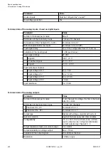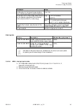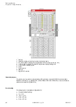
Internal data exchange
Analog inputs (words)
8
Analog outputs (words)
8
I/O configuration
The module does not store configuration data itself. The 8 configurable analog channels are
defined as inputs or outputs by the configuration, i.e. each of the configurable channels can
used as input or output (or re-readable output in case of voltage input/output).
When a channel is used as input, the corresponding output must be configured unused.
When a channel is used as output, the corresponding input must be configured unused.
Parameterization
Firmware version
Configuration
Firmware version > V2.0.0
The arrangement of the parameter data is per-
formed by Control Builder Plus/ Automation
Builder software.
The parameter data directly influences the functionality of modules.
For non-standard applications, it is necessary to adapt the parameters to your system configura-
tion.
Module: Module slot address: Y = 1...10
No.
Name
Value
Internal
value
Internal
value,
type
Default
Min.
Max.
EDS
Slot/
Index
1
Module
ID
Internal
1520
1
)
Word
1520
0x05f0
0
65535
0x0Y01
2
Ignore
module
2
)
No
Yes
0
1
Byte
No
0x00
not for
FBP
3
Param-
eter
length in
bytes
Internal
37
Byte
37-CPU
37-FBP
0
255
0x0Y02
4
Check
supply
Off
On
0
1
Byte
On
0x01
0
1
0x0Y03
5
Analog
data
format
Default
0
Byte
Default
0x00
0x0Y04
6
Behav-
iour of
outputs
at com-
munica-
tion
errors
Off
Last
value
Substi-
tute
value
0
1+(n*5)
2+(n*5),
n
£
2
Byte
Off
0x00
0
2
0x0Y05
Device specifications
I/O modules > Analog I/O modules
2022/01/31
3ADR010278, 3, en_US
419


