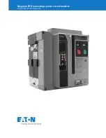
Series NRX drawout and breaker
three-way cable interlock installation
and removal instructions
m
WARNING
(1) ONLY QUALIFIED ELECTRICAL PERSONNEL SHOULD BE PERMITTED TO WORK
ON THE EQUIPMENT.
(2) ALWAYS DE-ENERGIZE PRIMARY AND SECONDARY CIRCUITS IF A CIRCUIT
BREAKER CANNOT BE REMOVED TO A SAFE WORK LOCATION.
(3) DRAWOUT CIRCUIT BREAKERS SHOULD BE LEVERED (RACKED) OUT TO THE
DISCONNECT POSITION.
(4) ALL CIRCUIT BREAKERS SHOULD BE SWITCHED TO THE OFF POSITION AND
MECHANISM SPRINGS DISCHARGED.
FAILURE TO FOLLOW THESE STEPS FOR ALL PROCEDURES DESCRIBED IN THIS
INSTRUCTION LEAFLET COULD RESULT IN DEATH, BODILY INJURY, OR PROPERTY
DAMAGE.
m
WARNING
THE INSTRUCTIONS CONTAINED IN THIS IL AND ON PRODUCT LABELS HAVE TO
BE FOLLOWED. OBSERVE THE FIVE SAFETY RULES:
– DISCONNECTING
– ENSURE THAT DEVICES CANNOT BE ACCIDENTALLY RESTARTED
– VERIFY ISOLATION FROM THE SUPPLY
– EARTHING AND SHORT-CIRCUITING
– COVERING OR PROVIDING BARRIERS TO
ADJACENT LIVE PARTS
DISCONNECT THE EQUIPMENT FROM THE SUPPLY. USE ONLY AUTHORIZED
SPARE PARTS IN THE REPAIR OF THE EQUIPMENT. THE SPECIFIED MAINTENANCE
INTERVALS AS WELL AS THE INSTRUCTIONS FOR REPAIR AND EXCHANGE MUST
BE STRICTLY ADHERED TO PREVENT INJURY TO PERSONNEL AND DAMAGE TO
THE SWITCHBOARD.
Instructions apply to:
UL489 Series NRX RF Frame
IEC IZMX40
Effective June 2016
Series NRX
Instruction Leaflet
IL01301060E