GE AKR-90-100, Installation Instructions Manual
The GE AKR-90-100 is a cutting-edge electrical circuit breaker with advanced features. Ensure smooth installation with our comprehensive Installation Instructions Manual, available for free download on our website. Get the manual now and explore the full potential of your AKR-90-100 from manualshive.com.
Share
Download


Reviews:
No comments
Related manuals for AKR-90-100

NH2-125
Brand: CHINT Pages: 6

DB-50
Brand: Westinghouse Pages: 40

De-ion DB-15
Brand: Westinghouse Pages: 43
RELION 650 SERIES
Brand: ABB Pages: 74

OLI
Brand: OEZ Pages: 6

OD-LT-VP01
Brand: OEZ Pages: 4

ARION WL Series
Brand: OEZ Pages: 316

T7-T7M-X1
Brand: ABB Pages: 12

SACE Tmax T6
Brand: ABB Pages: 5
S800U
Brand: ABB Pages: 2
S201-K5
Brand: ABB Pages: 6

Record Plus FB100
Brand: ABB Pages: 4
S 280 UC Series
Brand: ABB Pages: 16
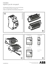
FH200A
Brand: ABB Pages: 2

F204 125 Series
Brand: ABB Pages: 2

Infinity NE-S
Brand: ABB Pages: 11

GE Power Break II GEH6271
Brand: ABB Pages: 10

Emax Series
Brand: ABB Pages: 10


