10-
54
T
roubleshooting
10
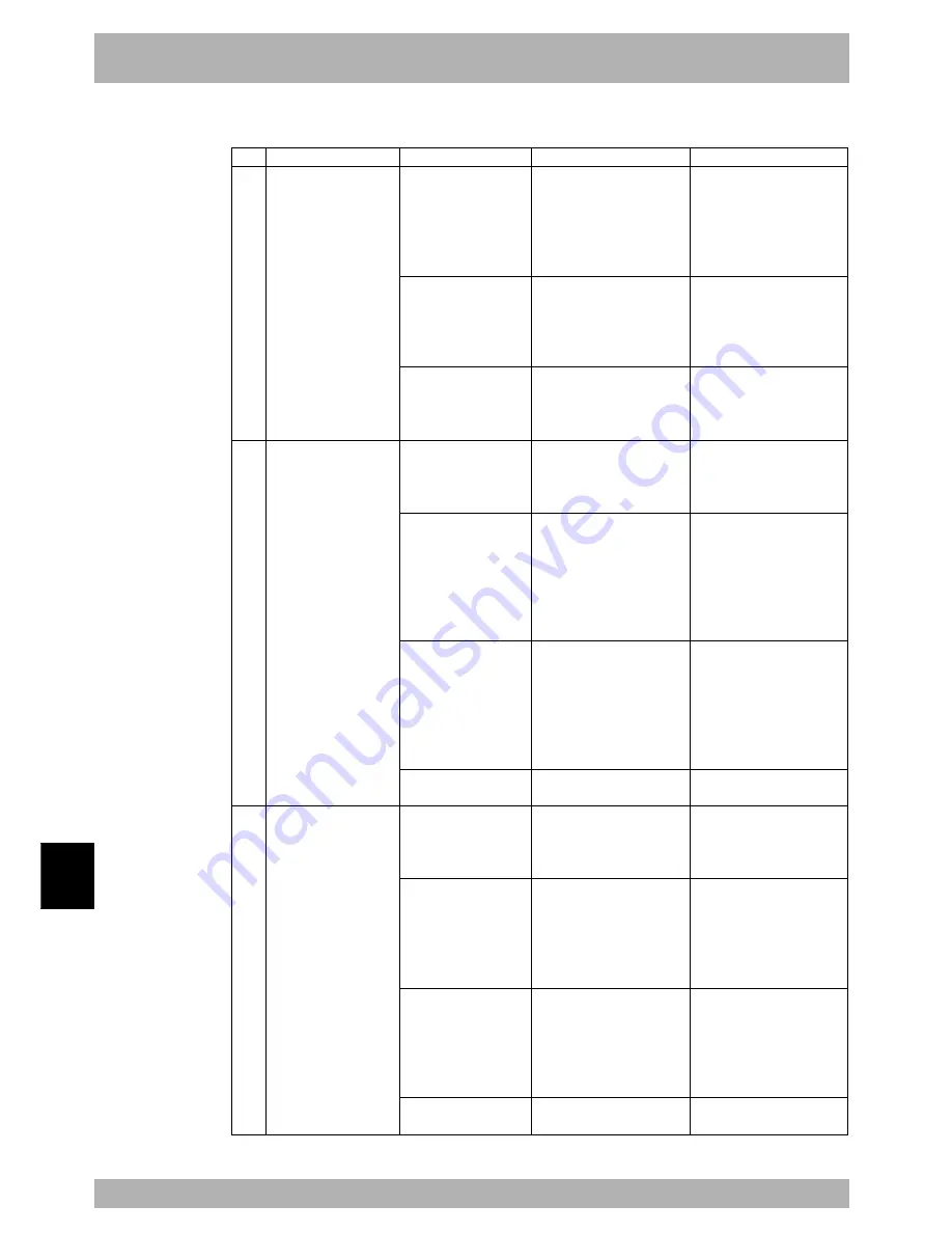
2. Troubleshooting
2. Robot operation
1
2
3
Symptom
Controller turns on but
can't execute program and
manual movement.
Abnormal sound or
vibration.
Position deviation
occurred.
• There are 2 main types of
position deviation.
1. Electrical position
deviation
2. Mechanical position
deviation
In case 1, if position
deviation occurs, you
can perform absolute
reset and return to
original position. In
case 2, you cannot
return to original
position.
Possible cause
• Interlock signal.
• Robot is in emergency
stop.
• Error occurred.
• Wrong robot or axis type
setting.
• Tip weight/ acceleration
settings are incorrect.
• Mechanical problem
occurred.
• Controller is defective.
• Position sensor device is
defective.
• Cable is defective.
• Position detection error
due to noise.
• Mechanical error
occurred.
• Controller is defective.
Corrective action
• Connect the standard I/O
interface connector for
interlock signal.
• Connect the DC 24V power supply.
• Disable interlock signal with
the parameter.
• Release MPB emergency stop
switch.
• Plug in MPB connector.
• Connect MPB emergency stop
terminal of SAFETY connector.
• Check the cause from the
error information.
• Eliminate the cause of the
error.
• Change to correct robot or axis
type setting.
• Make sure robot and controller
are compatible.
• Set a correct tip weight
parameter
• Set a correct “Accel.
Coefficient” parameter.
• Make a correct setting in the
program language.
• Reinforce the robot frame.
• Tighten the robot cover
screws.
• Remove foreign matter if
found.
• Replace if warped or damaged
guides or ball screws are found.
• If operation is normal use the
substitute controller.
• Replace motor if count is
incorrect.
• Replace cable if found to be
defective.
• Ground the robot and
controller.
• Isolate from noise sources
around robot.
• Isolate from noise sources
around robot I/O cable.
• Adjust to correct tension if
necessary.
• Remove foreign matter if
found.
• Replace guides or ball screws
if warping or damage is found.
• If operation is normal use the
substitute controller.
Check items
• Check standard I/O interface
connector (for interlock signal)
and check if DC 24V is
supplied.
• Check DI11 on MPB screen.
• Connect the MPB and check
error. information.
• Check DI00 on MPB screen.
• Connect the MPB and check
error info
• Check if “ERR” LED on front
panel is lit.
• Connect MPB and check robot
settings in SYSTEM mode.
• Check if robot and controller
are compatible.
• Check tip weight parameter
setting in SYSTEM mode.
• Check “Accel. Coefficient”
parameter setting in SYSTEM
mode.
• Check AXWGHT/ACCEL
commands in program language.
• Check for resonance in robot
frame.
• Check for loose screws on
robot cover.
• Check for warping or damage
on guides or ball screws.
• Replace with another
controller and check operation.
• Move axis in emergency stop
and check the pulse count.
• Check grounding of robot and
controller.
• Check robot periphery for
noise.
• Check for noise sources
around robot I/O cable.
• Check the belt tension
• Check for warping or damage
on guides or ball screws.
• Replace with another
controller and check operation.
Summary of Contents for RCX142
Page 1: ...User s Manual ENGLISH E YAMAHA 4 AXIS ROBOT CONTROLLER E92 Ver 1 09 RCX142 ...
Page 2: ......
Page 18: ...MEMO ...
Page 24: ...1 6 MEMO ...
Page 26: ...MEMO ...
Page 36: ...MEMO ...
Page 300: ...4 238 MEMO ...
Page 302: ...MEMO ...
Page 336: ...MEMO ...
Page 360: ...6 24 MEMO ...
Page 362: ...MEMO ...
Page 374: ...MEMO ...
Page 384: ...8 10 MEMO ...
Page 386: ...MEMO ...
Page 394: ...MEMO ...


