© 2008 - 2011 TOSHIBA TEC CORPORATION All rights reserved
e-STUDIO2020C/2330C/2820C/2830C/3520C/3530C/4520C
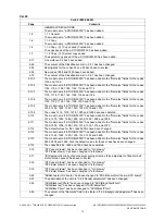
REVISION RECORD
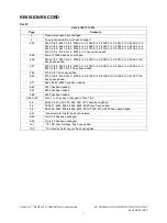
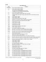
15
7-4
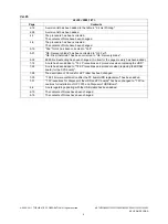
The illustration in Fig. 7-9 has been corrected.
7-5
The illustration in Fig. 7-12 has been corrected.
7-10
Step (3) in the content of the disassembling procedure in "7.1.11 Board Case" has been
divided to steps (3) and (4).
The illustration in Fig. 7-25 has been corrected.
The illustration in Fig. 7-26 has been corrected.
7-12
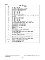
The content of "Fig. 7-28" in "7.1.12 SRAM board<for LGC board>" has been divided to
"Fig. 7-29" and "Fig. 7-30".
A note and an illustration Fig. 7-31 have been added.
7-13
The illustration in Fig. 7-32 has been corrected.
The content of "Fig. 7-30" in "7.1.13 SRAM board<for SYS board>" has been divided to
"Fig. 7-33" and "Fig. 7-34".
7-14
A note and an illustration Fig. 7-35 have been added.
7-18
The illustration in Fig. 7-37 has been corrected.
7-20
A new procedure has been added in step (1) in "[E] Replace / Format HDD”.
7-22
Descriptions in "7.2.4 Procedures and precautions when replacing the SYS board" has
been corrected.
7-23
A new procedure has been added in step (1) in "7.2.5 Procedures and settings when
replacing the SLG board".
7-24
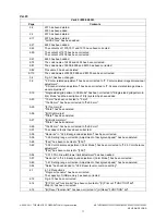
The title "7.2.6 Procedures and settings when replacing SRAM (SYS board)" has been cor-
rected to "7.2.6 Procedures and settings when replacing SRAM board (for SYS board)".
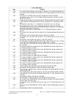
7-28
The title "7.2.7 Procedures and settings when replacing SRAM (LGC board)" has been cor-
rected to "7.2.7 Procedures and settings when replacing SRAM board (for LGC board)".
7-28
A new note has been added in "7.2.7 Procedures and settings when replacing SRAM board
(for LGC board)".
7-28
The introductory part of "7.2.7 Procedures and settings when replacing SRAM board (for
LGC board)" has been corrected.
7-28
The illustration of Fig.7-40 has been corrected.
7-28
The procedure in "[A] Replace SRAM board" has been corrected.
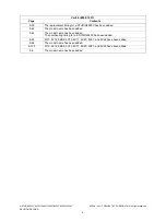
7-30
Descriptions in "7.3 Precautions for Disposal of the HDD and PC Boards" have been
corrected.
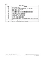
8-1
8. FIRMWARE UPDATING
Descriptions about the necessity of a harness jig for the converter firmware update have
been added.
8-2
E. Engine ROM
The illustration of the download jig has been corrected.
8-18
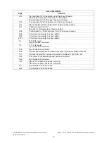
8.2.1 Writing the data to the download jig (PWA-DWNLD-350-JIG2) - [A] Precautions when
writing the System ROM data
A precaution "Loading the data file into the buffer by means of the following settings." has
been added.
8-18
8.2.1 Writing the data to the download jig (PWA-DWNLD-350-JIG2) - [A] Precautions when
writing the System ROM data-[A-1] System ROM
The name of the system ROM file has been corrected.
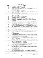
8-19
8.2.1 Writing the data to the download jig (PWA-DWNLD-350-JIG2) - [B] Precautions when
writing the Engine ROM data
Precautions when writing the Engine ROM data have been added.
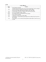
8-21
8.2.2 System ROM - [A] Update procedure
Step 9: The procedure for shutting down the equipment has been changed to turning OFF
the power with the main switch.
Step 10: The procedure for starting up the equipment has been changed to turning ON the
power with the main switch.
8-22
8.2.3 Engine ROM - [A] Update procedure
Step 1:The procedure has been corrected to "Write the ROM data to be updated to the
download jig (PWA-DWNLD-350-JIG2)."
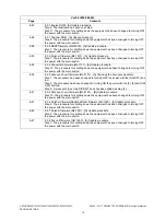
Ver.02 <2008.06.26>
Page
Contents

