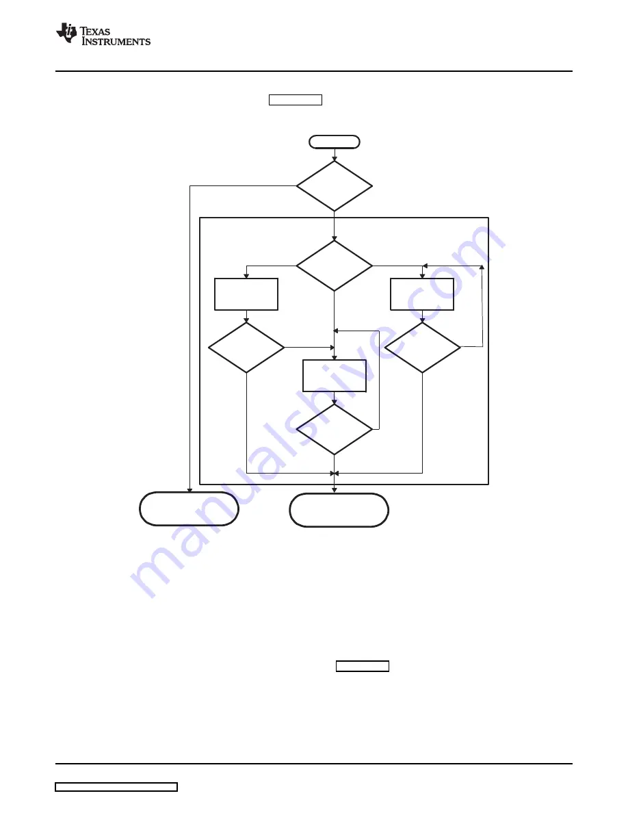
11.1.2 Functional Block Diagram
Boot
mode
?
Reset
Boot
mode
?
Boot from
NAND flash
Internal ROM
Boot OK ?
No
Yes
Boot from
UART
Boot from
MMC/SD
Boot OK ?
Boot OK ?
Yes
No
Invoke loaded
Program
Invoke
OneNAND
No
Yes
11.2 ARM ROM Boot Modes
11.2.1 NAND Boot Mode
www.ti.com
ARM ROM Boot Modes
The general boot sequence is shown in
.
Figure 11-2. Boot Mode Functional Block Diagram
DM335’s ARM ROM boot loader (RBL) executes when the BOOTSEL[1:0] pins indicate a condition other
than the normal ARM EMIF boot (BTSEL[1:0]
≠
01). In this case, control is passed to the ROM boot loader
(RBL). The RBL then executes the proper mode after reading the state of the BTSEL[1:0] pins from the
BOOTCFG register.
If the value in BTSEL[1:0] from the BOOTCFG register is 00, the NAND mode executes. The outline of
operations followed in the NAND mode is described in
. The NAND boot mode assumes the
NAND is located on the EM_CE0 interface, whose bus configuration is configure by the pins AECFG[3:0].
The pins AECFG[3:0] must be configured such that the proper EMIF signals are available for the NAND
device.
First, the device ID of the NAND device is read from the device, and then any necessary information (such
as the block and page sizes, etc.) are obtained from the device information table in the RBL. The device
information in the RBL is based on the list of supported NAND devices. Next, the RBL searches for the
UBL descriptor in page 0 of the block after CIS/IDI block (block 1).
SPRUFX7 – July 2008
Boot Modes
151


