


M1000/3000 Nova
Register 3
SPB7-230.033.11
Page 4 of 10
Siemens AG
Installation and Start-Up
Rev. 06
05.06
CS PS SP
Medical Solutions
20
-
4
Final
procedures
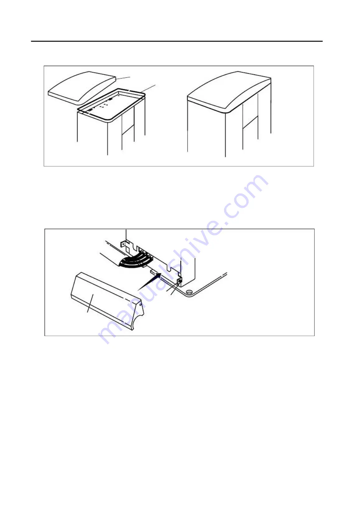
Fitting the MAMMOMAT cap
20
1. Fit the rubber strip on the edge of the stand (1).
2. Place the cap on the top of the MAMMOMAT (2).
Fitting the cable outlet cover
20
1. Fit the cable outlet cover (1) to the stand and fasten with screws (2) and contact
washers (3).
Fig. 2 MAMMOMAT cap
Fig. 3 Cable-outlet cover
M
A
M
0
0
6
2
6
M
A
M
0
0
6
2
7
1
2
M
A
M
0
0
1
3
0
2
1
3