


SerVision
Embedded Video Gateway System Guide
Configuring System Settings
33
7. In the
Save Settings
screen, click
Save Changes to System
. The unit stores the changes permanently, all
recorded video on the unit is erased, and the
System Restart Page
screen opens:
8. Click
Restart System
. The unit restarts, and the changes are implemented.
Setting the Unit Time
The unit has a built-in battery-backed clock that keeps track of the date and time even when the unit is turned off. It
is important to ensure that the time on the unit is accurate whenever the system is running; all video recordings
include timestamps that are derived from the unit's time, and playback relies on these timestamps. An inaccurate
clock can lead to misunderstandings when playing recorded video. Moreover, the unit will not record if the time on
it is invalid.
The clock can be set by manually synchronizing its time with the time on the PC on which the configuration utility
is running. This should be done when the system is first set up.
Like most clocks, the unit's clock has a tendency to drift slightly over time. Therefore, the time should be updated at
frequent intervals. The time can be updated manually at any time. The unit can also be configured to update its
clock automatically by connecting to an NTP time server at specified intervals. This option only works when the
unit has access to one or more NTP time servers, either public ones on the internet or locally-installed ones on the
LAN. Public NTP servers can be used free of charge and can be easily accessed when the unit has internet access.
MVG and CVG-M units can also be configured to update their clocks from GPS servers.
In addition to the time itself, the general time settings – time zone and daylight savings time (summer time) –
should always be configured correctly. The time zone and daylight-savings settings should be set correctly before
the clock is set. (After setting the time zone, be sure to click
Update
and restart the unit before manually updating
the time.) Daylight savings time can be activated manually or configured for automatic activation. When daylight
savings time is activated, the time on the unit clock is set one hour ahead of the time in the selected time zone.
To set the general time settings:
1. In the
Main Menu
, under
System
, click
Date & Time
. The
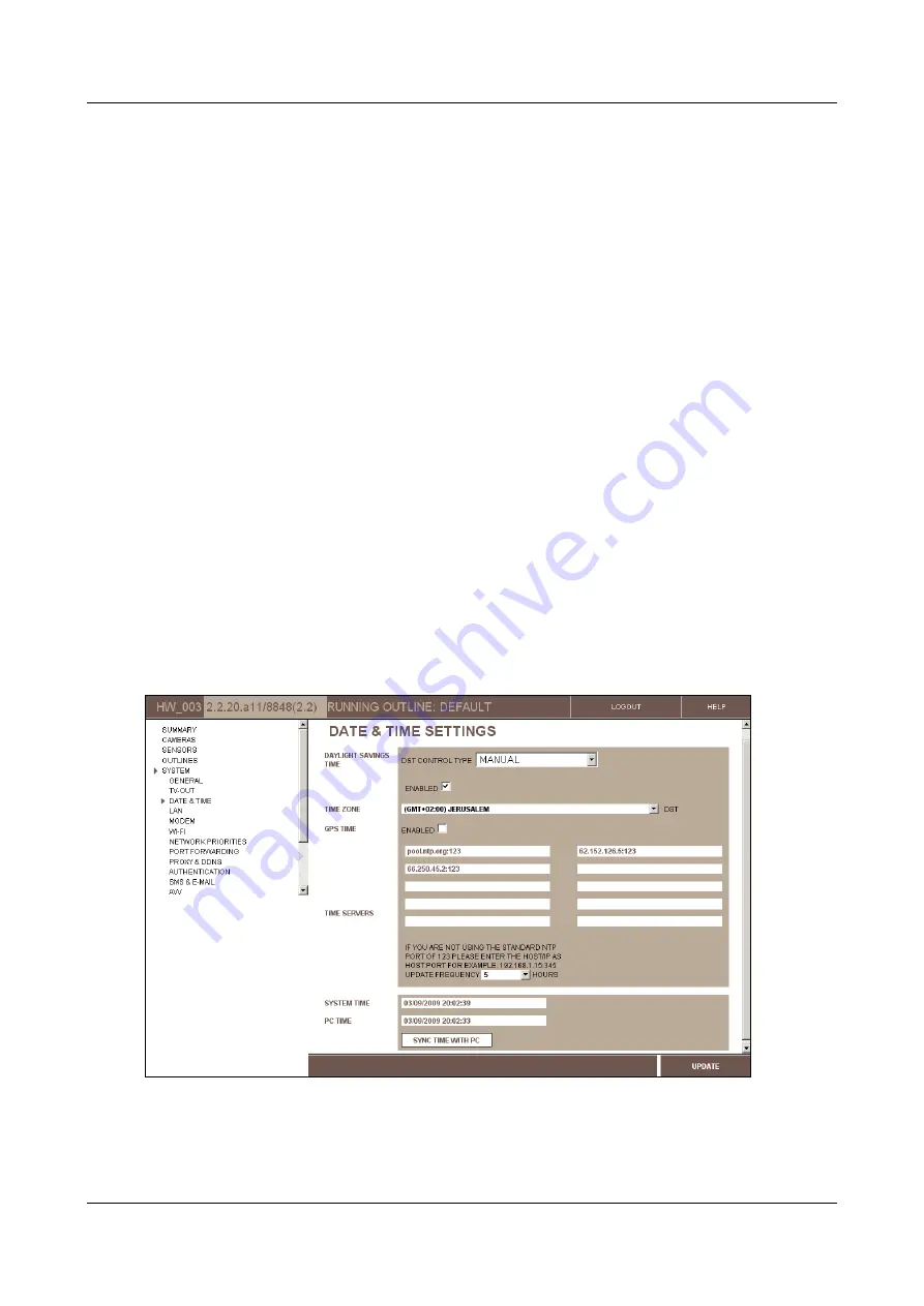
Date & Time Settings
screen opens:
Figure 27: Date & Time Settings screen (MVG)
Note:
The current date and time recorded on the clock of the Video Gateway unit appear in the
System Time
field.