32
The Sapling Company, Inc.
670 Louis Drive
Warminster, PA 18974
USA
P. (+1) 215.322.6063
F. (+1) 215.322.8498
www.sapling-inc.com
Temperature Sensor Installation - Optional Accessory
(
IMPORTANT:
Detach clock from power source before installing new circuitry. DO NOT add new circuitry
while the clock is operating)
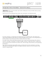
Attach the end of the Temperature Sensor Wire to the circuit board in the following manner:
The green connector is not designed to fit through the seal nut or gasket on the main board wiring
panel. After threading the cable through a seal nut and gasket of your choice on the wiring panel, use a
small screwdriver to secure the wires to the connector ports shown above.
The Sensor Cable is 6 feet (1.83 meters) long, and so the sensor should be positioned within 6 feet of
the clock. The cable is unshielded, 4 conductor, 22AWG (.33mm²). If longer than 6 feet is required, the
wire would have to be terminated in an electrical box, and the longer wire would have to be provided by
the customer.
Data from the temperature sensor will be sent to your clock when the clock is powered on. For more
information on how to make the digital clock display temperature, please see the section labeled “Web
Interface - Display Settings”.
3.3V, 100MA
3.3V, 100MA
Timer RX
Temp RX
Common
Timer TX
Temp TX
Not Used
Not Used
Input B+
Output A-
Output B+
Rly1 NO .5A 120vac/24vdc
Rly2 NO .5A 120vac/24vdc
User 1 Input
User 2 Input
User 3 Input
User 4 Input
Common
5V, 40MA
9 -12V, 40MA
Dukane Pulse
Dukane Reset
24Vac Sync
120Vac Sync
AC/DC Com
AUX
5V Dry Cont
(-) Neutral
(+) Line
Earth
1
1
1
1
1
J4
J5
J7
J10
J11
J9
RS485
Common
Input A-
5
5
4
8
10
24 VAC/DC
110/220 VAC
Sensor Cable
No W
ire in 5
White
Black
Gr
een
Red
5
4
3
2
1
Temperature
Sensor
J5


